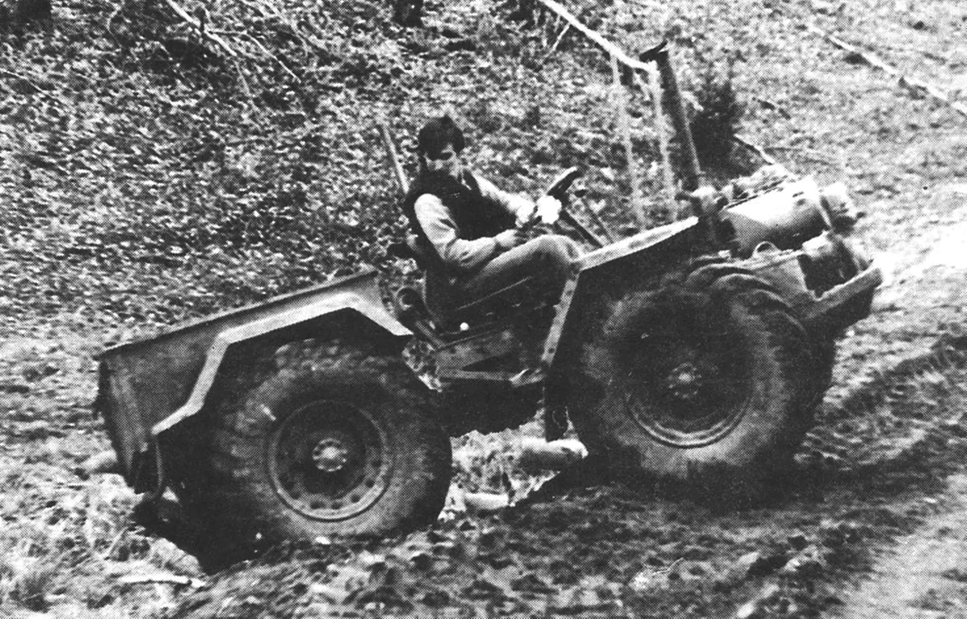
I invite the magazine’s readers to get acquainted with an original design of a universal self-propelled vehicle built by my brother Alexander. As he claims (jokingly, of course), the idea of making such a machine came to him out of laziness. He really did not want to spend his whole life doing hard, low-productivity work, because, unfortunately, in the countryside it is still not uncommon for a farmer to have to use grandfather’s agricultural implements.
In the settlement where my brother lives, 50% of walk-behind tractors and tractors are homemade; the rest are “Belarus” and “Vladimirets” machines. Here one should note the enormous role played by the magazine “Modelist-Konstruktor” in equipping rural households with small-scale mechanization equipment.
Nowadays the production of various walk-behind tractors is more or less established, but they are good for summer residents with their six hundred square meters. For cultivating 50 hundredths of a hectare of land, several hectares of hayfields, hauling fertilizers and the harvested crop, erecting farm buildings, and preparing fuel — especially under harsh Siberian conditions — one walk-behind tractor is not enough. What is needed is a compact, reliable, and inexpensive all-terrain tractor-tug with a set of mounted and trailed equipment.
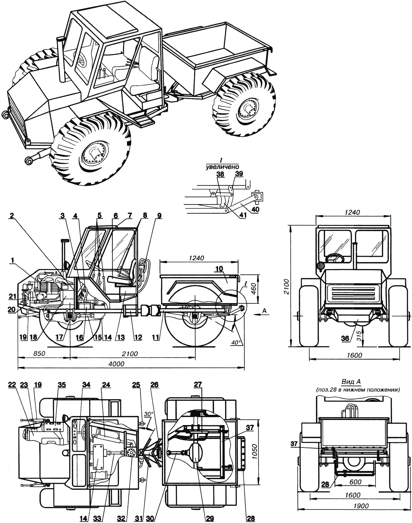
1 — engine; 2 — bulkhead; 3,4 — control pedals; 5 — gearshift and parking brake levers; 6 — seat; 7 — ventilation hatch; 8 — hydraulic drive control levers; 9 — hydraulic distributor; 10 — dump body; 11 — rear half-frame; 12 — front half-frame; 13 — hydraulic tank (fuel tank — on the right); 14 — transfer case; 15, 30, 33 — propeller shaft sections; 16 — gearbox; 17, 29 — axles with final drives and differentials; 18 — air filter; 19 — hydraulic cylinders of the bulldozer blade drive; 20 — gear-type hydraulic pump; 21 — fuel pump; 22 — fan; 23 — generator; 24 — steering hydraulic cylinder; 25 — filler neck; 26 — parking brake; 27 — hydraulic cylinder of the hitch drive and body lift; 28 — hitch board (St3, strip s20); 31 — housing of the rear half-frame hinge unit; 32 — load-bearing housing of the central hinge unit; 34 — steering column; 35 — battery; 36 — engine guard (St3, sheet s5); 37 — hitch pivot shaft; 38 — rocker (St3, sheet s20, 2 pcs.); 39 — body shackle (St3, sheet s20, 2 pcs.); 40 — hitch bar (St3, sheet s20, 2 pcs.); 41 — hitch board lift lever (St3, sheet s20, 2 pcs.).
Homemade builders mostly make tractors to the classic layout: the rear wheels, enlarged in diameter, are driving wheels, and the front ones are steered. Making such a tractor is not difficult, but as a rule it has insufficient cross-country ability and maneuverability, and its layout does not allow a body to be fitted without increasing the overall dimensions of the machine. Therefore the articulated-frame all-terrain layout chosen by Alexander is, in my view, optimal and can serve as a prototype for skilled people. The “Sibiryak” (as my brother named his creation) is almost entirely made up of ready-made assemblies and units: the D-21A1 engine comes from a “Vladimirets” tractor, and the rest from a GAZ-66 truck.
It all began with the magazine “Modelist-Konstruktor,” which our family had subscribed to since 1967. Alexander became keen on technical creativity as a 14-year-old teenager. First he built a simple aerosled, fitting a bicycle frame with an engine from a “Ural” chainsaw, a propeller, and skis. Some time later he assembled a sports motorcycle from spare parts. His next project was a two-seat all-terrain vehicle on low-pressure tires with an engine from an “Izh-Jupiter” motorcycle, which was operated year-round for several years.
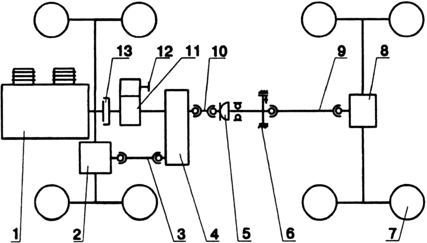
1 — air-cooled D-21A1 engine with generator, hydraulic pump, and fan; 2, 8 — final drives and cam-type axle differentials (i=6.83); 3, 9, 10 — propeller shaft sections; 4 — two-speed transfer case (gear ratios: i1 = 1.982, i2 = 1.0); 5 — constant-velocity joint; 6 — drum-type parking brake; 7 — wheel with 320×457 (12.00×18) tire; 11 — four-speed gearbox (gear ratios: i1 = 6.55, i2 = 3.09, i3 = 1.71, i4 = 1.0, reverse — i = 7.77); 12 — power take-off shaft; 13 — clutch.
After army service, Alexander’s design thinking took a more pragmatic direction. Together with his father he built a microtractor with a PD-10 engine. At the same time he designed and made a walk-behind hiller with an engine from a “Ural” chainsaw. In this way he gained the experience and knowledge needed to create a more powerful and complex machine, which he built in literally one year. Today it has become almost his only means of earning a living.
The hardest job turned out to be assembling the engine. At a scrap yard he found a written-off block from a T-25 “Vladimirets” tractor. The missing serviceable assemblies for it he bought from neighboring collective and state farms, and repaired the faulty ones.
The basis of the tractor is an articulated (“breaking”) frame, as on the “Kirovets.” It is welded from 80×80 mm square tubes with a wall thickness of 6 mm and consists of two half-frames linked by a hinge. Such a design has a number of advantages: it provides an even load on the wheels, thereby improving cross-country ability; it reduces stresses arising from bending and torsional moments; and it improves maneuvering characteristics, especially when traveling off-road and over rough terrain. Shortened by 200 mm axles (rear ones from a GAZ-66) are rigidly mounted on the frame with U-bolts, providing drive to all wheels. Mounted on the front half-frame are: the engine, gearbox, transfer case, electrical and hydraulic system assemblies, a cab with controls and instruments, and the fuel and hydraulic fluid tanks. On the rear half-frame are a welded dump body, the body hydraulic drive, a parking brake, and a hitch that can move in the vertical plane and is kinematically linked to the body. If necessary, by disconnecting the shackle it can move independently of the body. This design makes it possible to adjust plowing and hilling depth and facilitates hitching, towing, and maintenance. The hydraulics provide: a braking system for all wheels, the machine’s steering system, and drives for the bulldozer blade, mower, and rake. The machine is equipped with an electric starting system, a horn, and a searchlight.
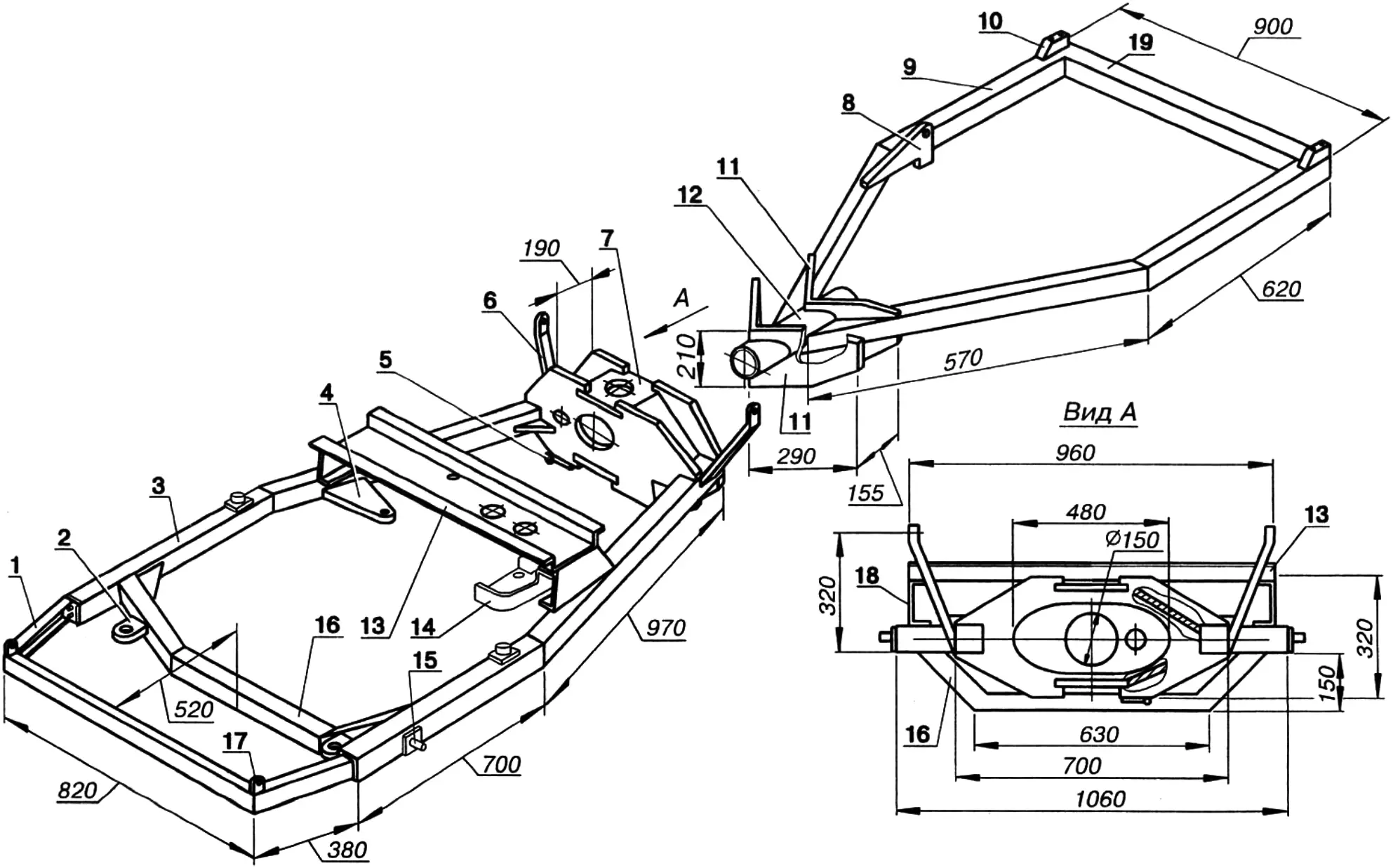
1 — bumper (St3, channel 80×80); 2 — engine mounting lug (St3, sheet s20); 3 — front half-frame side member; 4 — steering cylinder mounting bracket (St3, sheet s20); 5 — mower hitch lug (St3, sheet s20); 6 — cab mounting post (2 pcs.); 7 — central hinge unit housing (St3, sheet s20); 8 — bracket for the body-lift and hitch hydraulic cylinder (St3, sheet s20); 9 — rear half-frame side member; 10 — body mounting unit (St3, sheet s20); 11 — connecting plates; 12 — special hinge unit housing (steel 20, tube 150×10); 13 — beam for mounting the transfer case and cab floor (from GAZ-66); 14 — transfer case mounting bracket (from GAZ-66); 15 — blade hitch unit; 16 — crossmember (St3, tube 80x80x6); 17 — blade hydraulic cylinder mounting lug (St3, sheet s20); 18 — post (steel 20, channel 100×46); 19 — crossmember.
The “Sibiryak” is fitted with assemblies and systems from a GAZ-66 truck, although equipment from other vehicles can also be used. The four-speed gearbox provides travel speeds within 2.5–50 km/h and reverse. There is a power take-off (bolted to the clutch housing with studs) and a dry single-plate friction clutch.
A transfer case is mounted on the crossmember of the front half-frame; it distributes torque between the driving axles and can increase it. It also serves to drive mounted implements. Propeller shafts (from the same GAZ-66, but shortened) transmit torque from the transfer case to the final drives.
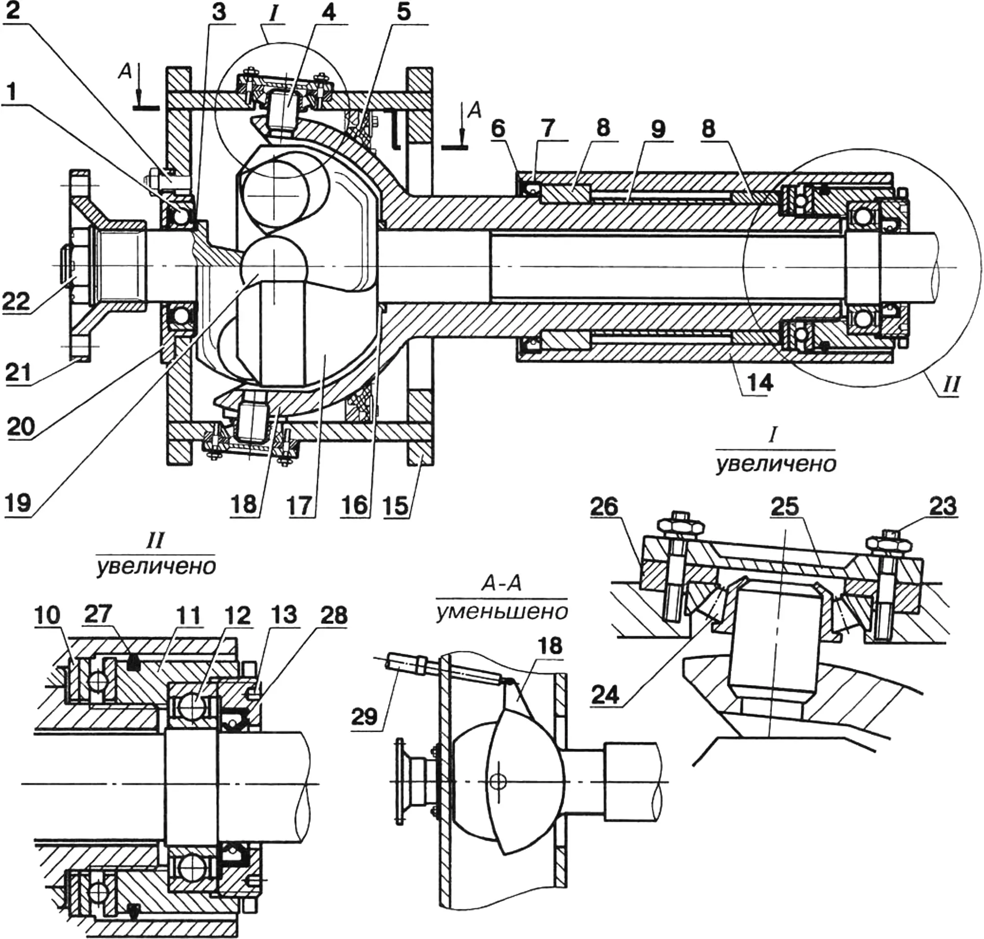
1 — bearing 60212; 2 — M10 stud (6 pcs.); 3, 10 — thrust rings (steel 45, s2); 4 — kingpin; 5 — seal (from the stock unit); 6 — spring ring; 7 — seal (1-115×145); 8 — bushings (bronze); 9 — spacer; 11 — thrust nut; 12 — bearing 8212; 13 — locknut; 14 — special housing; 15 — central hinge unit housing; 16 — ring; 17 — driven shaft; 18 — ball housing; 19 — driving shaft; 20, 26 — bearing housings (steel 45); 21 — flange (steel 45); 22 — M32 nut; 23 — M5 stud (6 pcs.); 24 — tapered bearing (stock); 25 — bearing cover; 27 — sealing ring (rubber); 28 — seal (1-85×110); 29 — steering hydraulic cylinder.
The most interesting part is the central hinge unit. It consists of a load-bearing housing that forms the rear part of the front half-frame, a constant-velocity joint (CV joint) that transmits torque to the rear axle, and a ball housing hinged in the load-bearing housing. The shank of the ball housing is inserted into a special housing of the rear half-frame and can turn in it when the relative position of the half-frames changes.
The special housing is connected to the rear half-frame by two 20-mm plates. The load-bearing housing, welded from 20-mm sheets, takes the loads acting on the machine in the vertical plane, while the ball joint, mounted in tapered bearings of the housing, serves to turn the half-frames relative to each other in the horizontal plane. This movement is effected by a steering hydraulic cylinder installed between the front half-frame and the ball-joint bracket.
The basis for the central unit was parts from the steering knuckle of the front wheel of a ZIL-131 truck, identical in design to the GAZ-66 but differing in size. The shank of the ball housing and the half-shaft shanks of the driving and driven CV-joint shafts were modified. The bearings in the axial hinge are bronze bushings, and the tractive (longitudinal) forces are taken by a thrust ball bearing. The hinge cavities are sealed with oil seals and packed with grease.
In the nose of the front half-frame, a bumper trapezoidal in plan is bolted at an angle of 15° to the half-frame plane; it also serves to mount the engine guard and hood.
The two-seat, two-door cab is welded from 25×25 steel angles and sheet iron. At the rear it is attached to the half-frame posts, and at the front to a transverse bulkhead installed behind the engine. The fenders are made of 2-mm iron; the rear ones are welded to the body, while the front ones are bolted to the bulkhead and frame. The cab floor rests on the crossmember that mounts the transfer case. The cab is fitted with seats whose backs can be adjusted within 10°. The seat position can also be adjusted to the height of the driver and passenger. The fuel and hydraulic fluid tanks are installed under the seats. The cab is glazed with heat-treated glass with rubber seals. Since summers in Siberia can be rather hot, there is a ventilation hatch in the roof. Outside, on the rear wall, a hydraulic distributor for the power cylinders is mounted.
Of the stock GAZ-66 steering system only the hydraulic booster remains; there are no mechanical drive elements. From the steering wheel the control force is transmitted through the steering column to a mechanism that acts on the distributor spool, which in turn directs fluid from the common hydraulic system into one or the other chamber of the power steering cylinder. The system operates only with the engine running, which drives the hydraulic pump.
The service brake system has four brake mechanisms (on all wheels) and a hydraulic drive. Pressure in the master brake cylinder is created by pressing the pedal. The brakes are drum, shoe-type. The parking brake is also a shoe brake with a mechanical drive, installed in the rear-axle transmission.
The electrical system (12 V) provides key-operated starter starting of the engine and powers the searchlight, horn, and instruments. It consists of a generator, battery, starter, relay-regulator, and starter switch.
The driver’s panel instruments include fuel quantity, engine oil pressure, and battery discharge indicators.
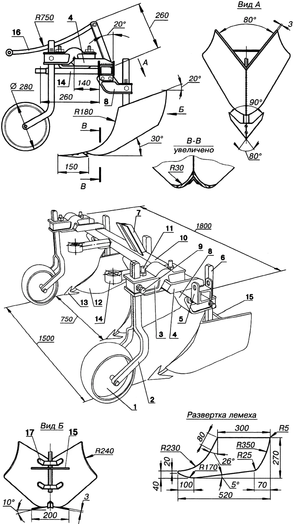
1 — support wheel 280×140 (from a farm machine); 2 — fork (St3, strip 40×8); 3, 11 — fork mounting parts (from a farm machine); 4 — half-frame (from a farm machine); 5 — sighting-bar mounting lug (St3, strip 40×8); 6 — blade post (St3, strip 50×20); 7 — upper link mounting bracket (St3, angle 50×50, 2 pcs.); 8 — blade post holder (from a farm machine); 9 — M16 locking bolt; 10 — crossmember 70×40 (from angle 70×70); 12 — blade share (St3, sheet s3); 13 — undercutter (St3, sheet s3); 14 — lower link (St3, rod Ø30); 15 — brace (St3, rod Ø10); 16 — upper link (St3, rod Ø30); 17 — clamp (St3, strip 25×4).
For the “Sibiryak” my brother built mounted and trailed equipment: a 2-share plow, a 3-share hiller, a rake, a mower, a bulldozer blade, a harrow, and a body trailer with a payload of up to 1.5 t. The machine and all its implements have shown high operating reliability and efficiency over ten years. Here are some figures characterizing its productivity: haymaking — 1 ha/h, raking — 1.5 ha/h, plowing — 0.2 ha/h, hilling — 0.25 ha/h.
The hiller, for example, is a trailed device with three blades, each consisting of two symmetrically arranged shares welded together along the front edge. Each blade is welded to a post and additionally secured with clamps. The posts are inserted into cast holders mounted on the crossmember. The holder design allows the blade height to be adjusted according to soil conditions. The support wheels can also be set to the required height and width.
The hiller is linked to the tractor by three links. The two lower ones are connected to the hitch board, and the upper one to the hitch shaft lever (in this case the shackle is disconnected from the body) and through it to the hydraulic cylinder, which makes it possible to control the mechanism promptly during hilling or when maneuvering in the field. The lugs at the ends of the crossmember are intended for mounting vertical sighting bars that help monitor hilling depth directly from the cab.
With the bulldozer blade one can uproot stumps up to 30 cm in diameter. The tractor easily tows a log up to 60 cm across.
Here I have given only a brief description of the “Sibiryak,” but anyone interested in this original all-terrain vehicle can form an idea of it and its capabilities.
MAIN TECHNICAL DATA OF THE “SIBIRYAK” TRACTOR
Mass, kg:
dry … 1300
gross … 2300
towed trailer … 1500
Maximum speed, km/h … 50
Minimum turning radius, m … 4.5
Engine … diesel D-21A1
Power, hp … 25
Cooling … air
Fuel tank capacity, L … 40
“Modelist-Konstruktor” No. 6’98, V. NIKONOV
Recommend to read
 CHICKEN “KINDERGARTEN”
The materials in the yard to get the chickens, make incubator, posted a lot. A wide range of mechanical designs "hens" from cardboard boxes with obogrevatel-LEM table lamp until... CHAIR-DESIGNER
With homemade furniture before the home the master always gets the main problem is how to connect individual parts which mount to choose, it was a simple, but reliable. The course is...
