When talking about the amateur constructor E. Kulikov, it should be noted that all the units and mechanisms he has made are designed to ease the labor and daily life of rural residents.
Let us touch upon one of the problems annually solved by village residents, and by those who live in most Russian settlements — preparing firewood for winter. Sawing “tree-lengths” into logs is the most labor-intensive stage in this process and takes a lot of time and effort if done manually. Chainsaws are far from being available to everyone, and they are not cheap. So villagers have to cooperate, using one saw for several households in turn. Well, splitting firewood can be done on free days in autumn or even in winter.
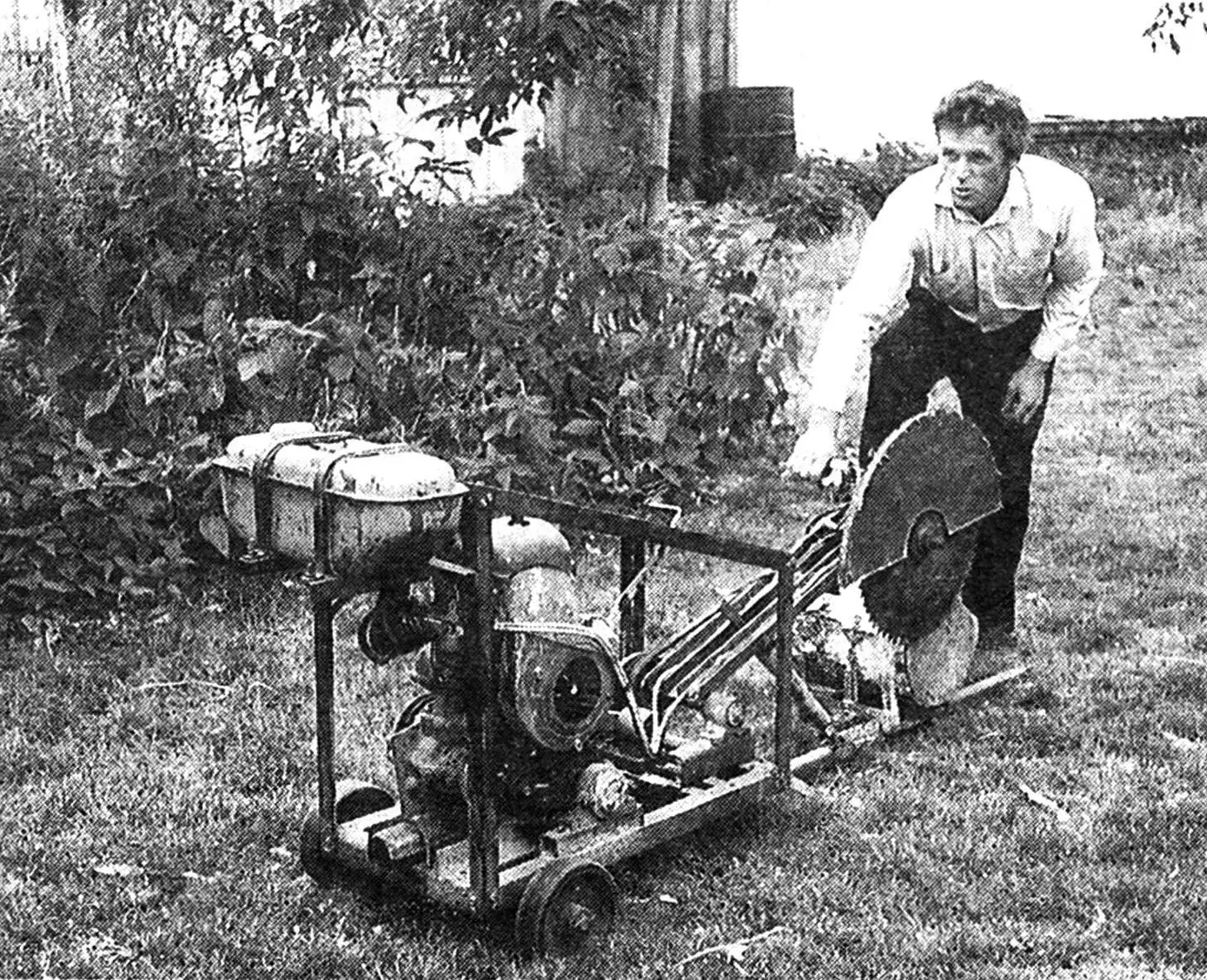
E. Kulikov, having assessed the situation, decided to make a semi-stationary pendulum saw of his own design. And he made it. Then it’s a matter of technique: start the engine — and just feed the log under the saw blade — cutting one log takes only a few seconds.
The saw consists of three main units: a frame with an engine and transmission units, a pendulum with a saw blade, and a drawbar with a receiving frame.
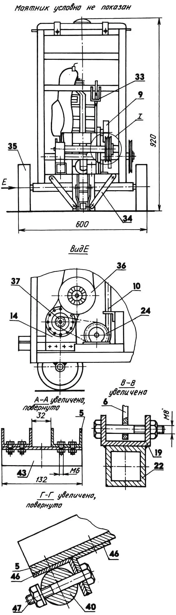
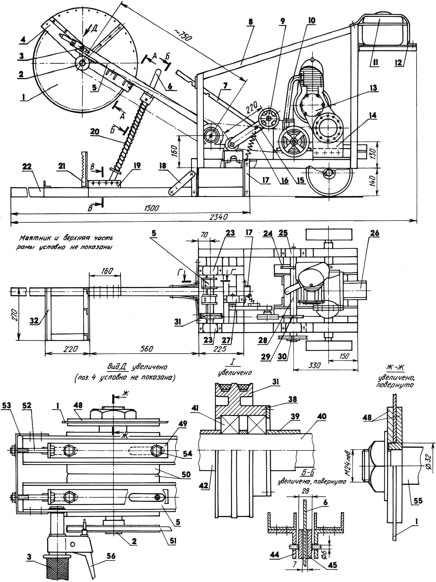
1 — saw blade (Ø480); 2 — driven pulley (Ø76); 3 — handle (from motorcycle); 4 — protective guard (St3, sheet s1); 5 — pendulum beam (St3, channel 50); 6 — return mechanism guide (St3, strip 25×5); 7 — intermediate belt tension mechanism stop (St3, strip 25×3); 8 — frame; 9 — tensioner roller (from agricultural machine); 10 — exhaust pipe; 11 — fuel tank; 12 — tank mounting strap (St3, strip 25х1,5, 2 pcs.); 13 — PD-8 engine; 14 — engine supports (steel 45, sheet s8); 15 — tensioner connecting rod (St3, tube 40x25x2); 16 — spring; 17 — post (St3, angle 32x32x4, 4 pcs.); 18, 34 — braces (St3, strip 25×3, 4 pcs.); 19 — return mechanism support (St3, channel 50); 20 — return spring; 21 — log stop (St3, angle 20x20x3, 3 pcs.); 22 — drawbar (St3, tube 40x40x5); 23 — pendulum axis bearing supports (from agricultural equipment); 24 — driven sprocket (z=20); 25 — intermediate shaft bearing support (from agricultural equipment); 26 — muffler (from “Voskhod” motorcycle, shortened and modified); 27 — connecting rod bearing support; 28 — intermediate shaft (from agricultural equipment); 29 — driving pulley (Ø117); 30 — engine starting pulley (Ø250, from agricultural equipment); 31 — double pulley (Ø117, from agricultural equipment, modified); 32 — receiving frame (St3, angle 40x25x3); 33 — stop loop (St3, rod Ø8); 35 — wheel (from agricultural equipment); 36 — engine forced cooling system guard (from T-200 engine); 37 — driving sprocket (z=10); 38 — lock ring (steel 45, s3); 39, 42 — spacers (steel 20, tube 34×1,5); 40 — pendulum axis (from agricultural equipment, Ø30); 41 — bearing 180206 (2 pcs.); 43 — crosspiece (St3, channel 50, 2 pcs.); 44 — return mechanism bracket (St3, angle 50x50x5, 2 pcs.); 45 — bushing (St3, welded); 46 — pendulum-to-axis mounting brackets (St3, angle 32x32x4, 2 pcs.); 47 — bolt M8 (4 pcs.); 48 — flanges; 49 — drive belt tension mechanism cam (St3, strip 25×5, 2 pcs.); 50 — driven shaft bearing units; 51 — drive belt 0 — 2000; 52 — bolt M8 (2 pcs.); 53 — clamp (St3, strip 25×5); 54 — bolt M10 (4 pcs.); 55 — driven shaft; 56 — throttle lever.
As the engine, a “starter” PD-8 from a T-40 tractor is used with a K-28G carburetor, a combined air filter, and an improved muffler from a “Voskhod” motorcycle. The reducer on the engine has been modified and the clutch drum has been removed. Brackets-plates for mounting the engine to the frame are installed under the flanges on the clutch side and the output gear. A forced air cooling system for the cylinder is also provided, borrowed from the T-200 motor scooter engine. The PD-8 is started with a cord placed in the groove of a special pulley on the intermediate shaft. The engine is controlled by a throttle lever of the motorcycle hand brake or clutch type, mounted on the pendulum handle.
Rotation from the engine to the saw blade is transmitted by one chain and two belt drives. The first belt drive, connecting the intermediate pulleys, also serves to connect the running engine to the blade instead of a clutch. This operation is performed by simply deflecting the tensioner roller connecting rod under the action of a spring. The primary shaft, installed in two bearing supports, rotates constantly. The pendulum axis, although located in bearing supports, rotates only when it moves up or down, and the double pulley mounted on it rotates in its own bearings independently of the shaft. The saw blade is secured to the driven shaft with two flanges and a nut with left-hand thread. Drive belt tension is adjusted by moving the shaft supports along the pendulum beams using a cam mechanism.
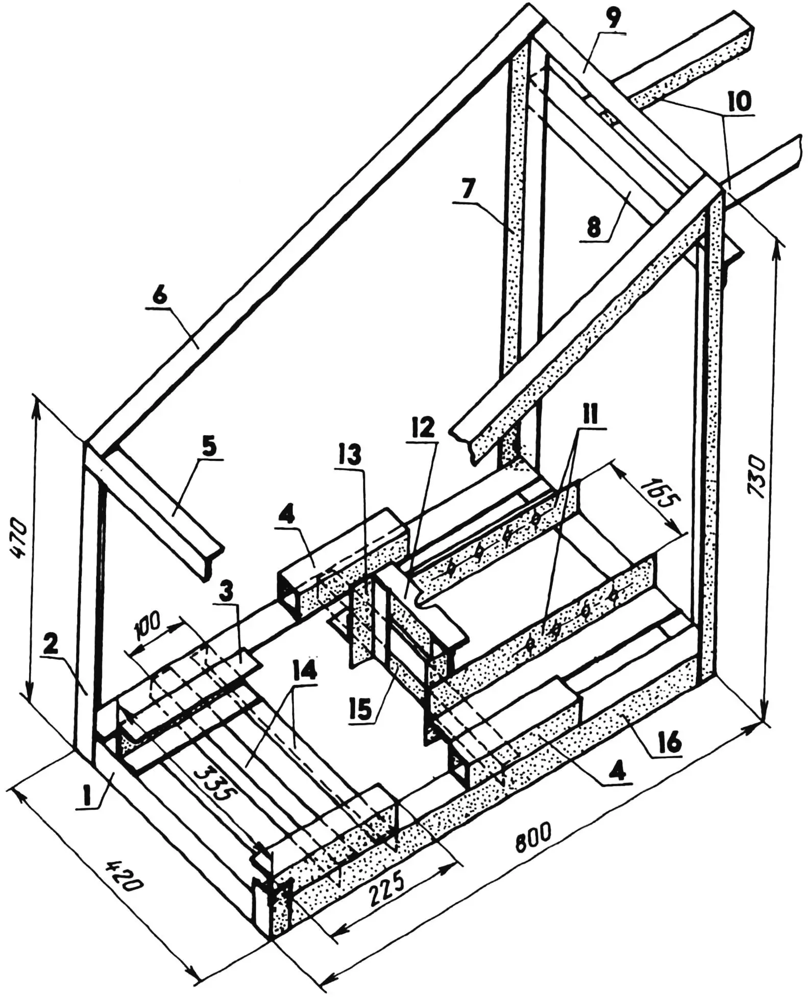
1 — cross member (angle 45x45x4, 2 pcs.); 2, 7 — posts (angle 36x36x4); 3 — pendulum axis support base (channel 50, 2 pcs.); 4 — intermediate shaft support bases (tube 40x40x4, L200); 5, 8, 9 — upper cross members (angle 36x36x4); 6 — diagonal brace (36x36x4, 2 pcs.); 10 — fuel tank mounting brackets (angle 36x36x4, L300); 11 — engine mounting side members (angle 70x70x7, L400); 12 — exhaust pipe stop (angle 36x36x4); 13 — stop post (angle 36x36x4, L250, 2 pcs.); 14 — roller tensioner support mounting beams (angle 36x36x4);
15 — engine mounting beam (angle 36x36x4); 16 — longitudinal beam (angle 45x45x4, 2 pcs.).
The saw frame is assembled from steel angles with bolts and then, for greater strength, welded. In its lower part, transverse beams, side members, and pads for mounting the engine and bearing supports of intermediate shafts are laid. At the top there are brackets on which the fuel tank is placed. It is finally secured to the frame with two steel straps. A tube is welded to the longitudinal frame beams at the bottom, into which wheel half-axles are inserted.
The drawbar is a continuation of the frame, as it is rigidly connected to it by two pairs of posts and braces. It is made of rectangular section tube and serves to move the unit, as well as its front support. A receiving frame with three stops designed to prevent the log from rotating, and a pendulum return mechanism support are welded to the drawbar.
The pendulum consists of two parallel beams located 32 mm apart and connected to each other by crosspieces. At one end, a saw blade enclosed in a guard is installed, and at the other, the pendulum is attached directly to the axis using two angles and bolts. In the non-working state (when the blade is disconnected), the pendulum is at a certain angle to the horizontal so that the blade does not interfere with log feeding. Raising the pendulum after each cut and holding it in this position is done by a return mechanism, which includes: an adjustable support, a guide, a spring, two brackets connected to the pendulum beams, and a bushing pivotally suspended between the brackets. When the pendulum moves, the guide slides freely in the bushing. The spring is selected so that during the working stroke it does not particularly impede the operator’s effort, but reliably returns the pendulum to the upper, i.e., initial position. The protective guard of riveted construction is made of sheet steel. To hold it on the pendulum, the guard is equipped with three strap-brackets that are bolted to the beam.
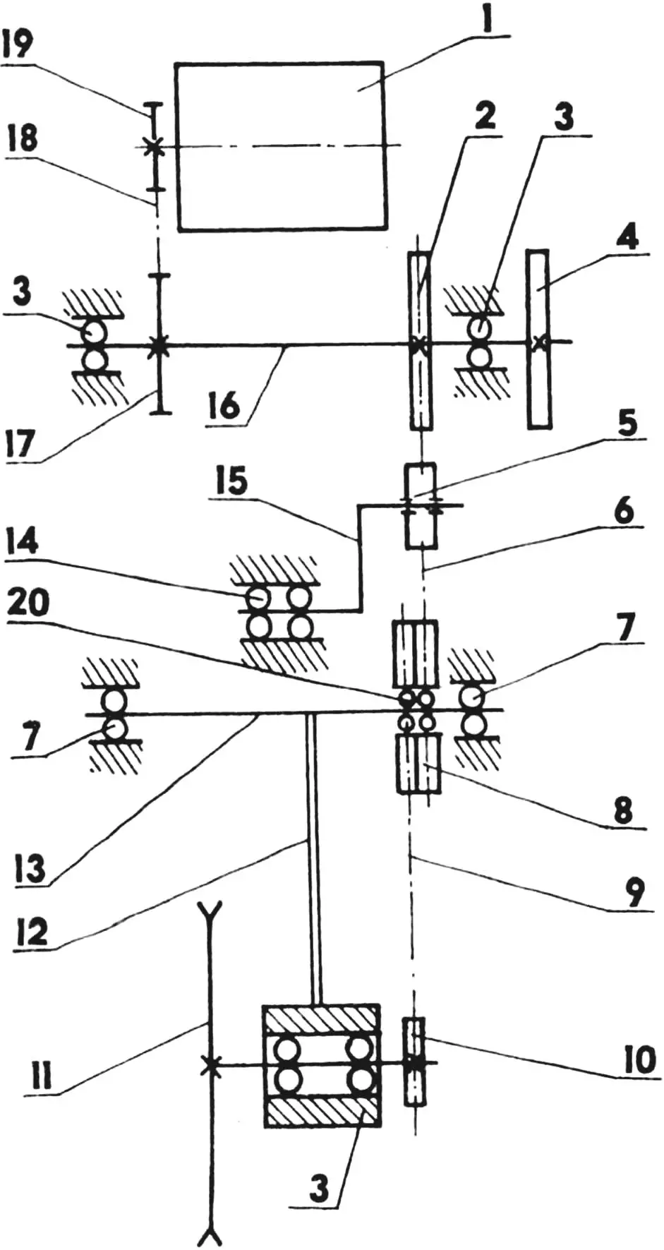
1 — engine; 2 — pulley (Ø117); 3 — ball bearings 11206; 4 — engine starting pulley; 5 — tensioner roller; 6, 9 — belts; 7, 14, 20 — ball bearings 180206; 8 — double pulley (Ø117); 10 — driven pulley (Ø76); 11 — saw blade; 12 — pendulum; 13 — pendulum axis; 15 — connecting rod; 16 — intermediate shaft; 17 — sprocket (z=20); 18 — chain; 19 — sprocket (z=10).
The operating procedure for a saw of this design is quite simple. First, the operator makes sure that the intermediate belt tensioner and pendulum are raised (the intermediate belt is not tensioned, its engagement with the pulleys is absent). Then he places the log that needs to be sawn into logs in the receiving frame and starts the engine. Removes the tensioner from the stop and, lowering the roller, tensions the belt, thereby connecting the intermediate pulleys to each other. The saw blade begins to rotate. By pressing on the pendulum handle, the operator lowers the saw and cuts off a log. At the same time, depending on the density and structure of the wood, he adjusts the blade speed with the throttle lever. Subsequently, he performs all operations in reverse order up to disengaging the clutch, which is necessary to ensure operator safety when feeding the next log.
The description of E. Kulikov’s pendulum saw would be incomplete if we did not mention that it has been faithfully serving the owner and his neighbors for about ten years now.
V. KUDRIN
Recommend to read
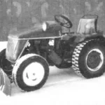 MICROTRACKER “BEE”
Almost from childhood read the magazine "modelist-Konstruktor". It has taught a lot of information about new designs, interesting ideas. Inspired by the publication in the journal, while... STAIRS… KNOTS
Both in the construction and further operation or repair of individual or country house to work on the roof required a special ladder, better wood, with an l-shaped end at the top so you...
