Timer “school”, published in “M-K” № 12 in 1986, is a unique combination of reliability, service life and good flight properties. Now that our group operated two such machines, we can safely say that. It should be noted that “loss” in sports-related accidents time, unfamiliar to us. Believe it or not, in such main circuit, accurate Assembly of the frame on the plasticized resin and Mylar covering to break the model, even with strongly uprated engine is almost impossible! Of course, strength isn’t everything. But the important and time-saving Modeler, especially spending on “nasty” repairs. So, now all the “repairs” been reduced to mere convergence of the split nodes. At the same time with extraordinary strength achieved and very high rigidity of the machine, which is extremely important for engine model.
But after the final debugging of this timemay no equal in the stability of the engine rise, and sustainability in planning (and this is with a smooth Mylar covering!). The model is not critical to the direction and strength of the throw and forgiving even gross errors at startup. The average time of flight with a modified motor “Junior” is more than 3 min, thus overlapping the most stringent requirements for the “school” technique. Results serial engine more modest. On average, MK-17 with the standard screw stably extracts timesnow the result of 1.5 minutes is Not too much, you say? But if you’re at all familiar with the problems of youth modeling, then you will appreciate the fact that such a model almost never happens launches “zero”?
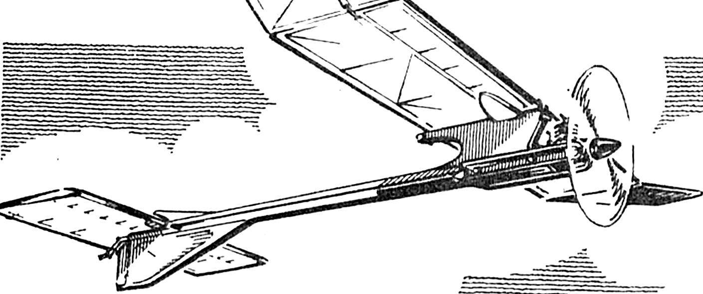
Last modification timarchi this scheme is very close to the model-prototype, at least, not inferior to it in performance. And changed this. Most importantly, the car became even more compact (it is even stronger). With a decrease in amplitude could be expected to reduce the time of planning. But, apparently, positively affected the increase of the chord, respectively, and Reynolds numbers: planning the short model is not inferior to the prototype. Went for the benefit and installation of two vortex generators that complement the ability of the exposed edges of the stringers to turboservice air flow. Note that socks ribs on the new model are mounted not for the sake of profiling, but as a means of increasing the hardness of the set and the leading edge. Simplified mounting of the wing — now it is clearly fixed on the pylon due to poluchaemyh protrusions of the Central rib that goes in the socket on the upper end of the pylon. Rubber ring goes through the front pin and the rear ledge pillar platform. Ears hung on to short the pins of the wire OVS Ø 2.5 mm and pulled rubber bands (segments of the nipple tube), put on and glued to the ribs “ears” and the center of micrococci. Themselves “ears” are shorter on one section.

 Timer “school”, published in “M-K” № 12 in 1986, is a unique combination of reliability, service life and good flight properties. Now that our group operated two such machines, we can safely say that. It should be noted that “loss” in sports-related accidents time, unfamiliar to us. Believe it or not, in such main circuit, accurate Assembly of the frame on the plasticized resin and Mylar covering to break the model, even with strongly uprated engine is almost impossible! Of course, strength isn’t everything. But the important and time-saving Modeler, especially spending on “nasty” repairs. So, now all the “repairs” been reduced to mere convergence of the split nodes. At the same time with extraordinary strength achieved and very high rigidity of the machine, which is extremely important for engine model.