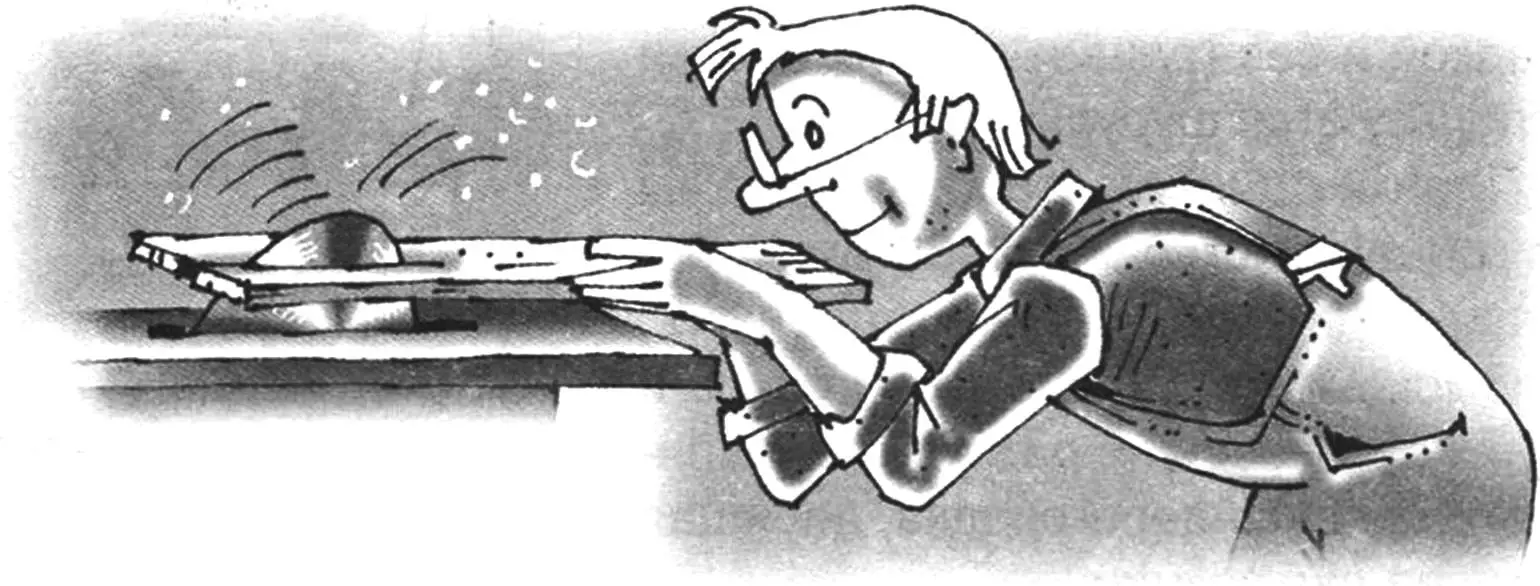
Almost all DIYers love working with wood, and many prefer this material to all others and make practical and beautiful things from it. But to seriously engage in woodworking (even if it is a hobby), it is clear that one knife is not enough. In this case, it would be nice to have a wood-cutting machine in your home workshop – even if it is small, tabletop, but multifunctional.
Of course, such woodworking machines are available for sale. However, you are unlikely to find one without an electric motor. And this unit has significant dimensions and weight, which is completely unacceptable for a tabletop machine. And the price of a machine with a motor increases significantly. But you can make a machine yourself (a description and drawings of such a machine are given below). Its design is simple, and those units and parts that you cannot make yourself (there are very few of them) can be ordered from specialists.
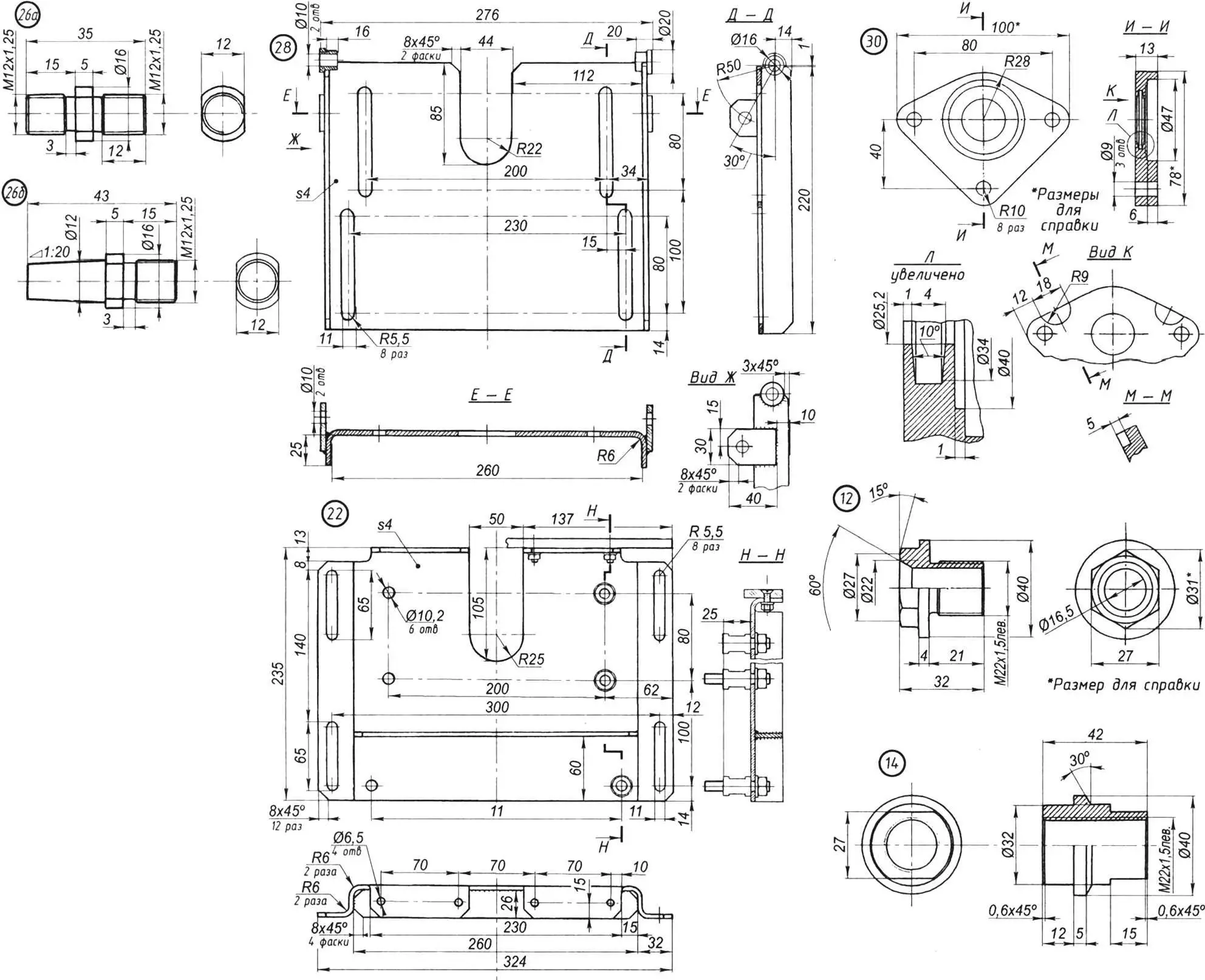
The main feature of the machine, compared to industrial ones, is that it does not have its own engine, and a regular electric drill with a bushing-nozzle installed instead of a drill chuck can be used as one. Depending on the type of the output shaft of the electric drill, one of the corresponding bushings is installed on it, which has a threaded or conical hole inside. On the outside, both bushings are processed to a square with sides of 15×15 mm.
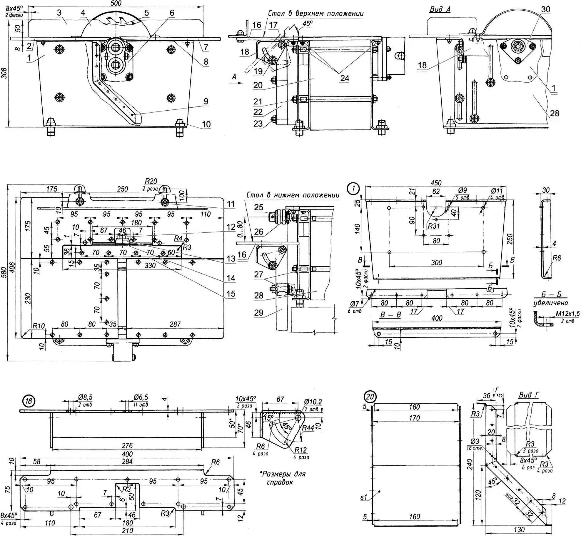
1 — right side wall with pins (St3, sheet s4); 2 — plane table feed plate (D16AT, sheet s8); 3 — stop (St3, sheet s4); 4 — saw blade casing (St3, sheet s1); 5 — saw blade (purchased product); 6 — gearbox; 7 — plane table feed plate (D16AT, sheet s8); 8 — lining (D16AT, sheet s1,2, 2 pcs.); 9 — rivet Ø3 with semicircular head for fastening tray (as needed); 10 — adjustable leg with M20 lock nut (4 sets); 11 — stop lock, M10 bolt with washer and nut (4 sets); 12 — saw blade clamp (screw М22х1, 5 left, steel 30ХГСА, circle Ø40); 13 — saw blade clamping ring (steel 25, circle Ø40); 14 — saw blade adapter sleeve (steel 30ХГСА, circle Ø40); 15 — raised (inner) frame bar (D16AT, sheet s8); 16 — tilt-lower table plate (D16AT, sheet s8); 17 — table tilt axis (bolt М10, 2 sets); 18 — tilt-lower table base (steel 20, sheet s4); 19 — table tilt lock (bolt М10, 2 sets); 20 — spacer tray (steel 10, sheet s1); 21 — tie (stud M10 with nuts and washers, 4 sets); 22 — lifting frame (steel 20, sheet s4); 23 — frame retainer (bolt M10, 4 sets); 24 — table plate fastening (bolts M6 with countersunk head as needed); 25 — chuck; 26 — tip “a” or “b” (steel 30KhGSA); 27 — spacer sleeve M10 (steel 30KhGSA, circle Ø18, 10 pcs.); 28 — left side wall (St3, sheet s4) with bushings (St3, circle 20, 2 pcs.); 29 — lowering frame (St5, sheet s4); 30 — bearing cage (D16AT)
The support part of the machine is formed by two side walls made of 4 mm thick steel sheet. The walls are made with flanges: the work table plates are attached to the upper flanges using M6 bolts and screws, and adjustable-height legs are screwed into the corresponding threaded holes in the lower flanges.
At the top in the middle of the side walls, identical grooves are cut for the gear shaft of the reducer and the tool shaft of the cutting head. The reducer housing is attached to one of these walls using four studs, and the bearing cage is attached to the other.
In the middle between the side walls, an inclined tray for removing chips and sawdust is fixed. The tray is made of a 1 mm thick steel sheet with flanges, with which it is riveted to the side walls. At the top, the tray is attached with M6 bolts to the inner edge of the front plate of the table.
When the side walls are pulled together with four long M10 studs (two on each side – at the top and bottom), the tray acts as a spacer.
All replaceable cutting tools, which provide the machine with versatility, are mounted on one cutting head. It is a drum, to which the tool shaft is attached with a cylindrical pin on one side. The other side of the drum is mounted on the drive shaft-gear and connected to it with the same cylindrical pin. The landing sockets on both sides of the drum are the same. In the standard version, four knives are installed on the drum – they give the machine the function of an electric planer. This number of knives (usually two or only one) ensures high productivity even with a relatively low power of the electric drill, as well as good quality of the planed surface.
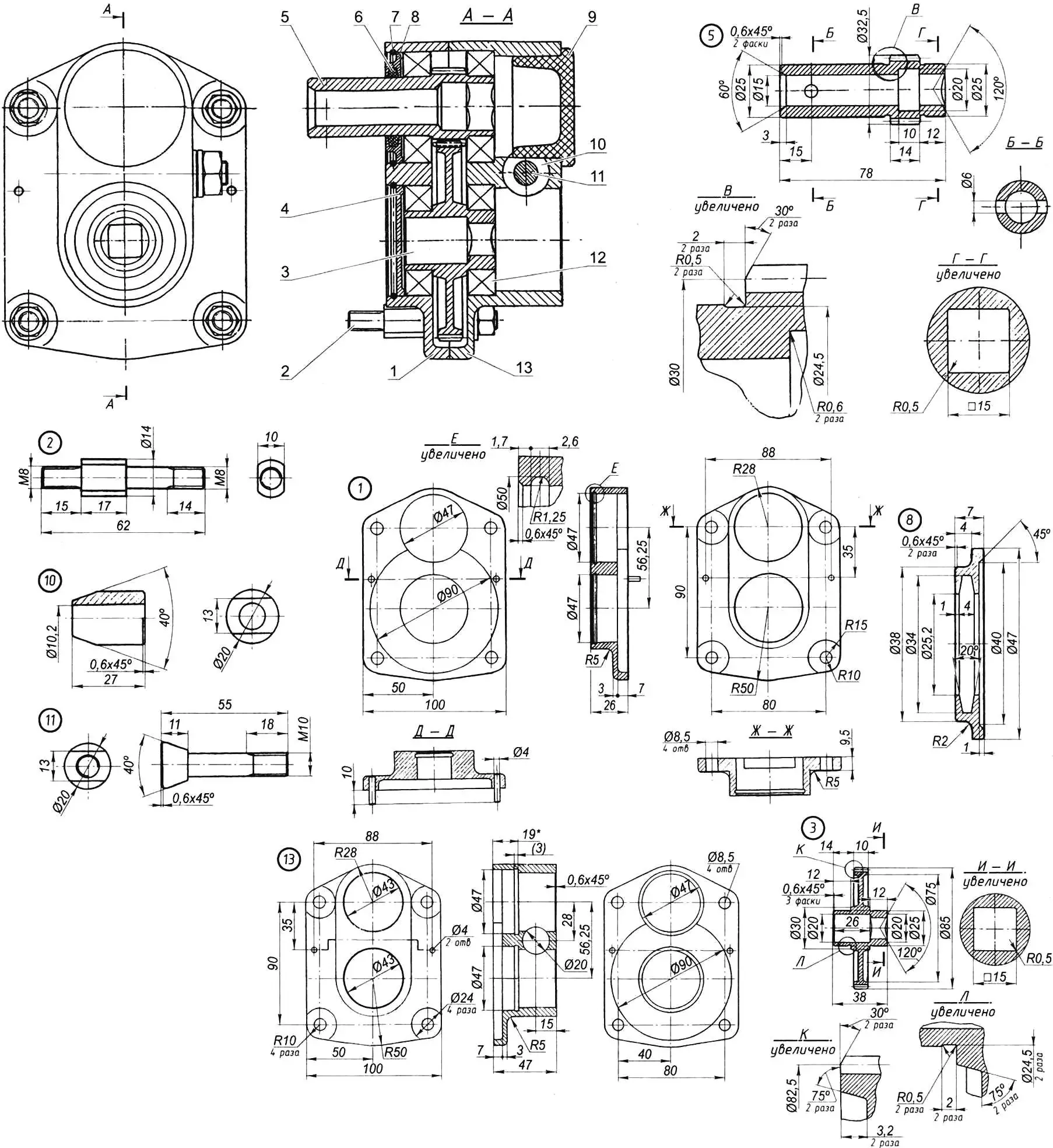
1 — inner part of the housing (aluminum alloy AL-9); 2 — stud M8 with washer and nut (4 sets); 3 — gear wheel z = 66, m = 1.25 (steel 30KhGSA, circle Ø85); 4 — lower plug (St5, sheet 3); 5 — pinion shaft z = 24, m = 1.25 (steel 30KhGSA, circle Ø33); 6 — gland seal (felt); 7 — retaining ring (wire IIA Ø2.5, 2 pcs.); 8 — upper plug (St5, sheet s8); 9 — plug (polyamide 610); 10 — bushing (steel 25, circle Ø20); 11 — special bolt (steel 30KhGSA, circle Ø20); 12 — bearing 80105 (4 pcs.); 13 — outer part of the housing (aluminum alloy AL-9)
If necessary, strips of sandpaper for finishing or felt for polishing parts can be attached to the drum.
The main “assortment” of replaceable wood-cutting tools is fixed on the tool shaft, inserted into the socket in the end of the drum and fixed there with a cylindrical pin. The middle part of the shaft rests on a bearing in a cage mounted on the side wall of the machine.
The main tool is the saw blade. It is mounted on a transition sleeve, previously screwed onto the console threaded end of the shaft and clamped through the ring with a special screw. The thread on the parts (both external and internal) is M22x1.25 left, so that the disk does not turn away under load.
Other tools are fixed in a drill chuck, screwed or mounted on a tip, which is screwed into the corresponding threaded hole in the end of the shaft. Here the thread is normal – M12x1.25, right-hand.
The gearbox is single-stage, step-up, with a gear ratio of 2.75. If the electric drill has a maximum RPM of about a thousand, then the plane or saw blade will rotate at a frequency of 2500 – 3000 RPM. This rotation speed is quite sufficient for cutting chipboard and hard wood. The direction of rotation of the drum (and therefore the knives of the plane and saw blade) will be counterclockwise (opposite to the direction of rotation of the drill).
At the same time, 1000 rpm of the tool is quite sufficient for drilling and milling. In this case, the drive operates with a gear ratio equal to one. To do this, the drill tip must be inserted into the other (upper) socket of the gearbox.
The gearbox gears are cylindrical and straight-toothed. The wheel has 66 teeth, the pinion shaft has 24. The tooth module is 1.25. Each gearwheel is mounted in two radial ball bearings 80105 with protective washers on both sides. To prevent wood dust from entering the gearbox from the cutting head side, the bearings are covered with plugs, and on the output shaft the plug is equipped with a gland seal.
The gearbox housing consists of two parts. Both parts are made of aluminum alloy AL-9. The most important dimensions in both parts of the housing that must be maintained are the bearing seats, the center distances between them, and the alignment. Therefore, it is better to order these parts, as well as the gear wheels, from specialists.
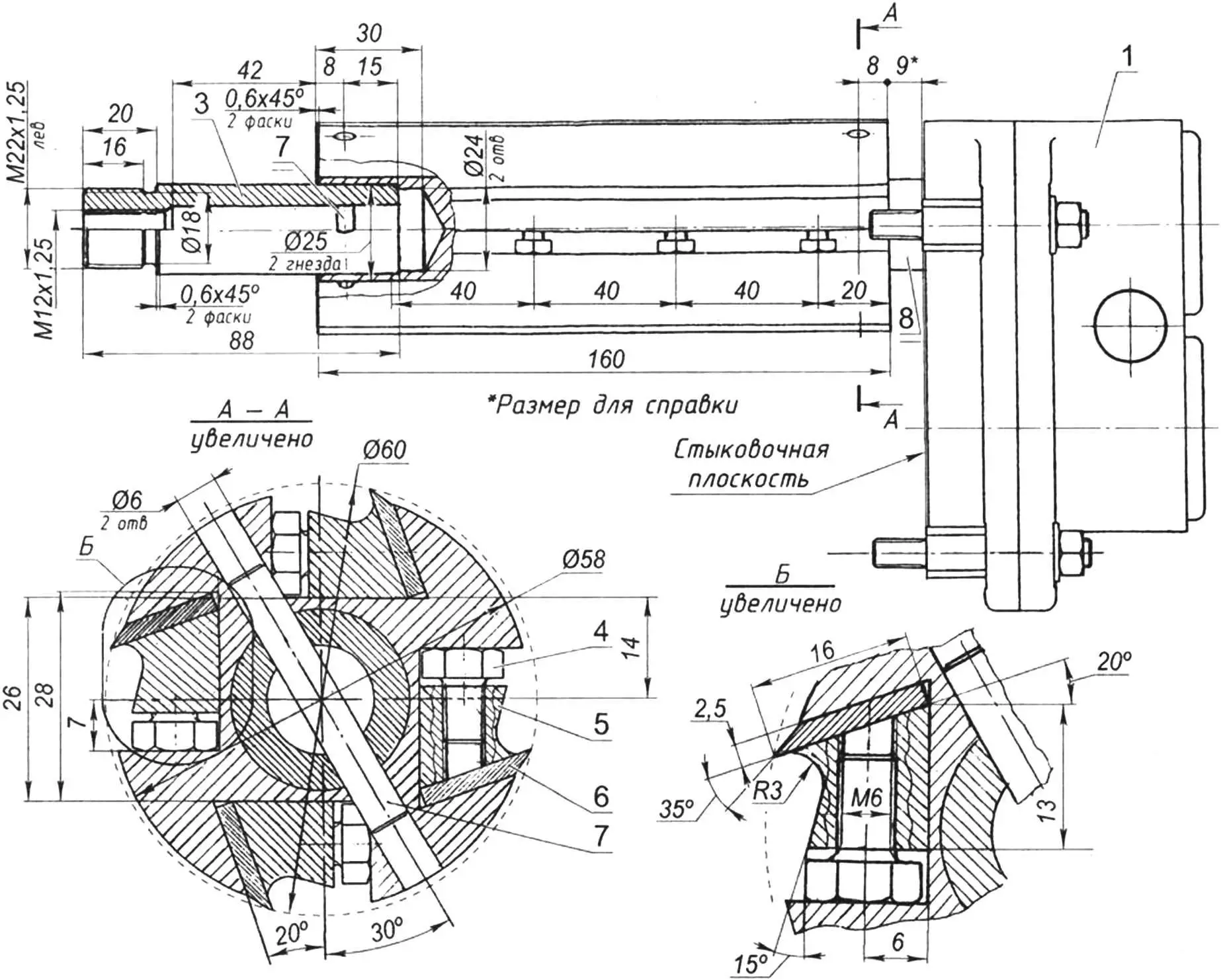
1 — gearbox; 2 — drum (steel 25, circle Ø58); 3 — shaft (steel 30KhGSA, circle Ø25); 4 — screw M6 (16 pcs.); 5 — clamp (steel 25, circle Ø20, 4 pcs.); 6 — knife (steel 50KhFA, sheet s2.5); 7 — pin (steel 20, circle Ø6, 2 pcs.); 8 — gear shaft of the gearbox
The versatility of the machine is largely ensured by the lifting bar and the rotary-lowering table, mounted on separate frames. The frames and the bar are fixed to the side wall on the opposite side from the gearbox, and the table frame is fixed to it. The vertical grooves made in the frames allow them to be rearranged, moving both frames up from the initial position (from the plane of the plane) up to 55 mm or the table frame down up to 80 mm. In this case, the lowering table plate can also be rotated at an angle of up to 45°.
The side table can be raised to change the cutting depth of the saw blade, tilted to allow cutting of workpieces at an angle, and lowered to allow convenient work with different tools.
In conclusion, I will provide a list of the main operations that can be performed on the machine:
1. Planing boards up to 160 mm wide.
2. Longitudinal sawing (cutting) of boards up to 50 mm thick.
3. Cross-cutting (and at an angle) of boards of the same thickness.
4. Selection of grooves and folds.
5. Longitudinal and transverse milling.
6. Drilling holes (straight and at an angle).
7. Grinding and polishing.
And the last thing. Instead of a saw blade or in a chuck on a mandrel, you can install an abrasive wheel or cylinder. And then on the machine you can sharpen wood-cutting tools and even process metal parts.
E. EVSIKOV
Recommend to read
 VELCRO… THE DOOR
Tenacious as burrs, Velcro is not a problem: you can buy new and old things to use. And that's what — and I want to offer: let holds the door open. How? A piece of Velcro stuck to the... FIRST — FREEZE
Not so easy to drill a hole in laminated or foamed material. However, if he is able to absorb water — you can use a witty way, received in due time, even the copyright certificate. The...
