An apparatus for gas cutting and welding of various materials, including refractory metals, would hardly be unwanted in any household. Especially a compact one that is completely safe to handle. But where can you get such a device? And for many people buying one is simply out of reach.
Yet among supporters of small-scale mechanization — enthusiasts who like to make everything with their own hands — such an apparatus is surely already available. Possibly even a homemade one, built from sketches and recommendations published in the pages of Modelist-Konstruktor (No. 7, 1980 and No. 10, 1985).
How to make an improved version of a compact yet fairly powerful apparatus for gas cutting and welding, operating on the principle of producing a hydrogen–oxygen combustible mixture by electrolyzing an aqueous alkali solution, is the subject of this magazine article.
I have had my first “water torch,” capable of cutting and welding even refractory metals, since 1985. I made it (and have now set up small-batch production of similar units for sale) from materials published in Modelist-Konstruktor. Now I present to readers my latest design, based on an electrolyzer that, although improved (a greater number of working plates, modified side boards, and a reliable fitting for the outlet of the combustible gas mixture), still operates on the same principle.
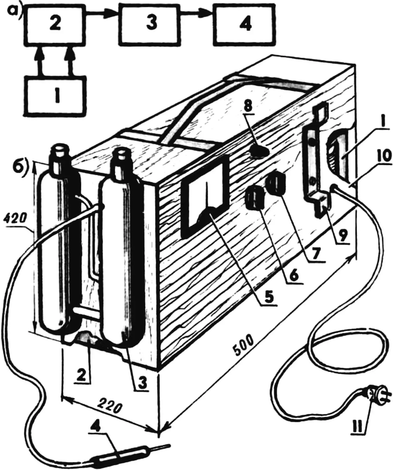
a — block diagram, b — finished homemade design; 1 — power supply unit with rectified mains voltage, 2 — electrolyzer, 3 — liquid seal, 4 — gas torch, 5 — ammeter, 6 — apparatus on/off knob, 7 — operating-mode knob (stepwise change of power delivered to the load), 8 — potentiometer control knob, 9 — clip for storing the power cord coiled up, 10 — portable wooden case, 11 — plug.
For those encountering such a device for the first time, it seems useful to explain in the most general terms (and to remind others) what the essence of this type of design is. And it is fairly simple.
Between the side boards, connected by four studs, metal electrode plates are placed, separated by rubber rings. The inner cellular cavity of such a battery is filled to 1/2…3/4 of its volume with a weak aqueous alkali solution (KOH or NaOH). Voltage from a DC source applied to the plates causes decomposition (electrolysis) of the solution, accompanied by abundant evolution of hydrogen and oxygen. This gas mixture, after passing through a special liquid seal (Fig. 1a), goes on to the torch and, when burned, provides the high temperature so necessary for many technological processes (for example, cutting and welding metals) — about 1800°C.
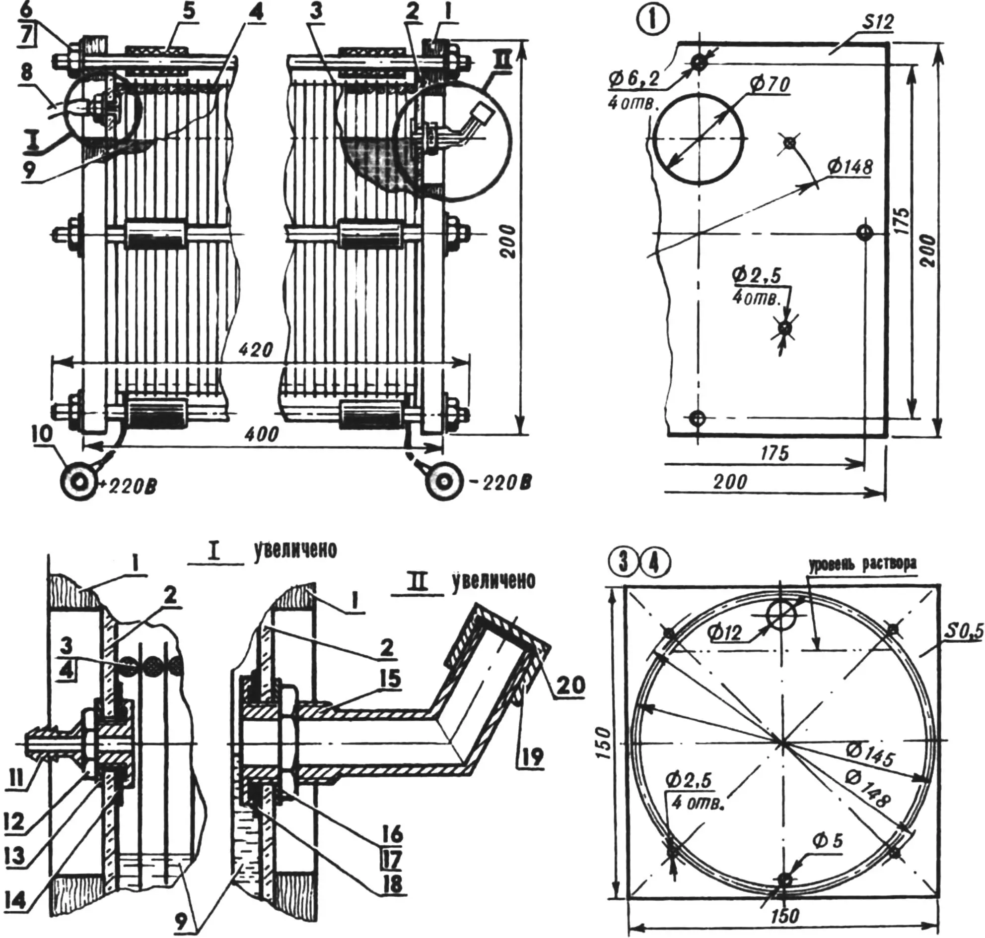
1 — side board (plywood, s12, 2 pcs.), 2 — transparent cheek (acrylic glass, s4, 2 pcs.), 3 — electrode plate (sheet metal, s0.5; 81 pcs.), 4 — separating sealing ring (5-mm acid- and alkali-resistant rubber, 82 pcs.), 5 — insulating bushing (cambric tubing 6.2×1, L35, 12 pcs.), 6 — M6 stud (4 pcs.), 7 — M6 nut with lock washer (8 pcs.), 8 — combustible gas mixture outlet tube, 9 — weak alkaline solution (2/3 of the electrolyzer’s internal volume), 10 — contact terminal (refined copper, 2 pcs.), 11 — fitting (stainless steel), 12 — M10 union nut, 13 — fitting washer (stainless steel), 14 — collar (acid- and alkali-resistant rubber), 15 — filler neck (stainless steel), 16 — M18 union nut, 17 — filler-neck washer (stainless steel), 18 — sealing washer (acid- and alkali-resistant rubber), 19 — filler-neck cover (stainless steel), 20 — sealing gasket (acid- and alkali-resistant rubber).
The electrolyzer’s output depends on the alkali concentration in the solution and other factors. Most importantly, it depends on the size and number of electrode plates and the distance between them, which in turn is determined by the parameters of the power supply unit — power and voltage (at about 2…3 V per galvanic gap between two adjacent plates).
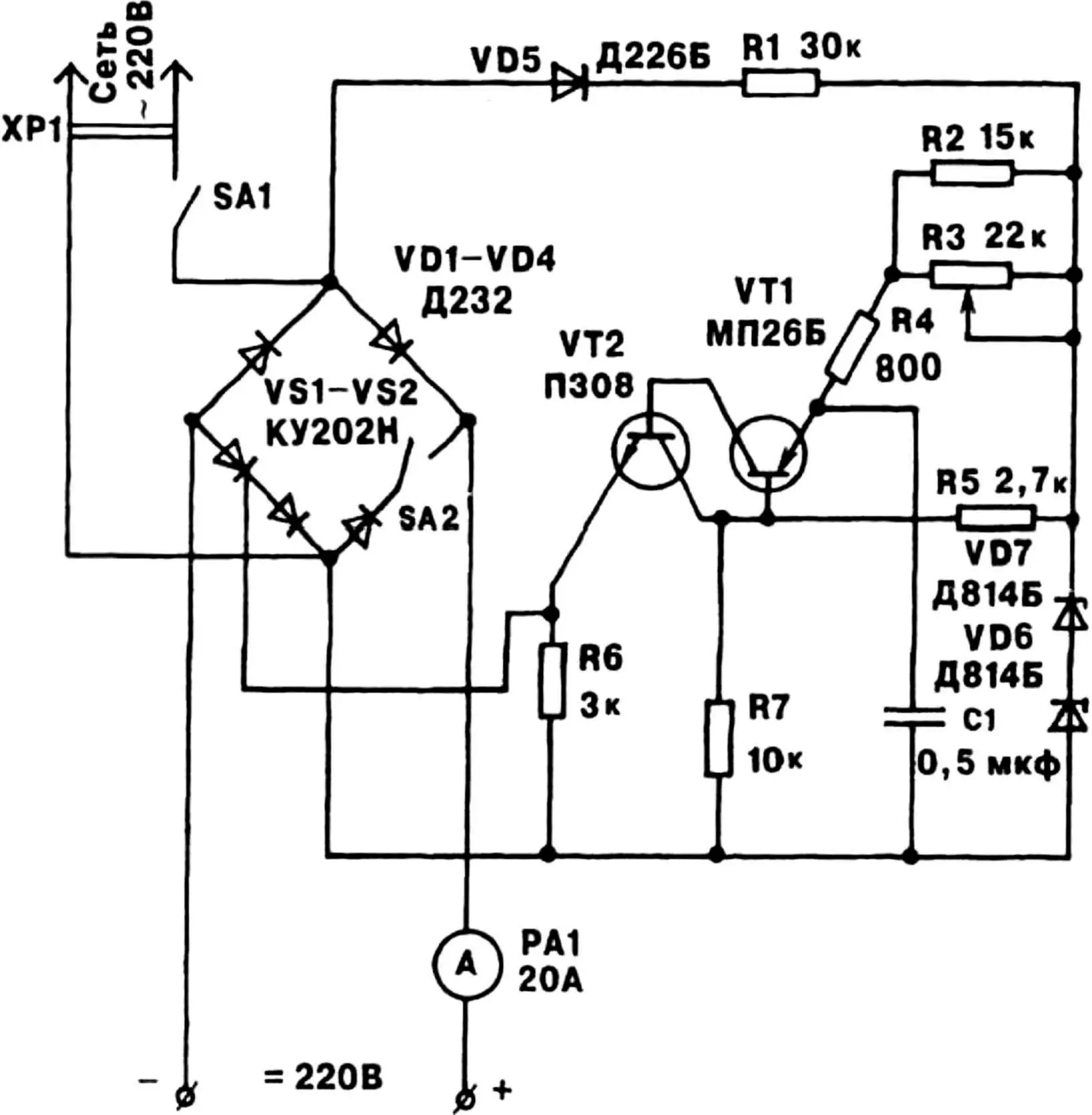
The DC power source designs I propose are feasible to make in a “home workshop,” even for a beginner. They can ensure reliable operation of even an “eighty-cell” electrolyzer (81 electrode plates) and, of course, of a “thirty-cell” one. The version whose schematic is shown in Fig. 4 also makes it easy to adjust power for optimal matching to the load: on the first stage — 0…1.7 kW, on the second (when SA1 is switched on) — 1.7…3.4 kW.
The plates for the electrolyzer are proposed accordingly — 150×150 mm. They are made from 0.5-mm roofing sheet iron. In addition to a 12-mm gas-outlet hole, four mounting holes (2.5 mm in diameter) are drilled in each plate; during assembly, knitting or bicycle spokes are passed through them. The spokes improve centering of the plates and gaskets and are therefore removed from the assembly at the final stage.
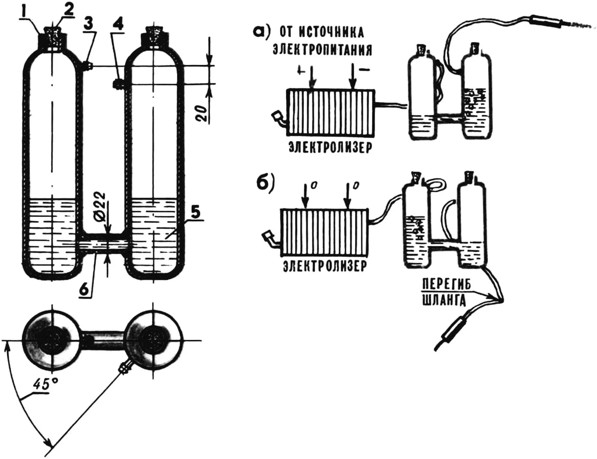
1 — cylinder (2 pcs.), 2 — plug (2 pcs.), 3 — inlet fitting, 4 — outlet fitting, 5 — kerosene, 6 — adapter (steel pipe).
In general, it took a good deal of thought before the “water torch” became as convenient and reliable as Edison’s lamp: switch on — it works; switch off — it stops. The most troublesome part was modernizing not the electrolyzer itself, but the liquid seal connected to its outlet. Once the almost template-like use of water as a barrier against flame propagating back into the gas-generating battery (through the connecting tube) was abandoned in favor of… kerosene, everything immediately fell into place.
Why kerosene specifically? First, unlike water, this liquid does not foam in the presence of alkali. Second, practice has shown that if kerosene droplets accidentally enter the torch flame, the flame does not go out — only a slight flash is observed. Third, while serving as a convenient “separator,” the kerosene in the seal proves fire-safe.
At the end of work, during a break, and so on, the torch is naturally extinguished. A vacuum forms in the electrolyzer, and the kerosene flows from the right tank into the left one (Fig. 3). Then comes air bubbling, after which the torch can be stored as long as desired: it is ready for use at any moment. When it is switched on, the gas presses on the kerosene, which again flows into the right tank. Then gas bubbling begins…
The connecting tubes in the apparatus are polyvinyl chloride. Only a thin rubber hose leads to the torch itself. So after the power is switched off, it is enough to pinch this rubber hose by hand — and the flame, after a light pop, goes out.
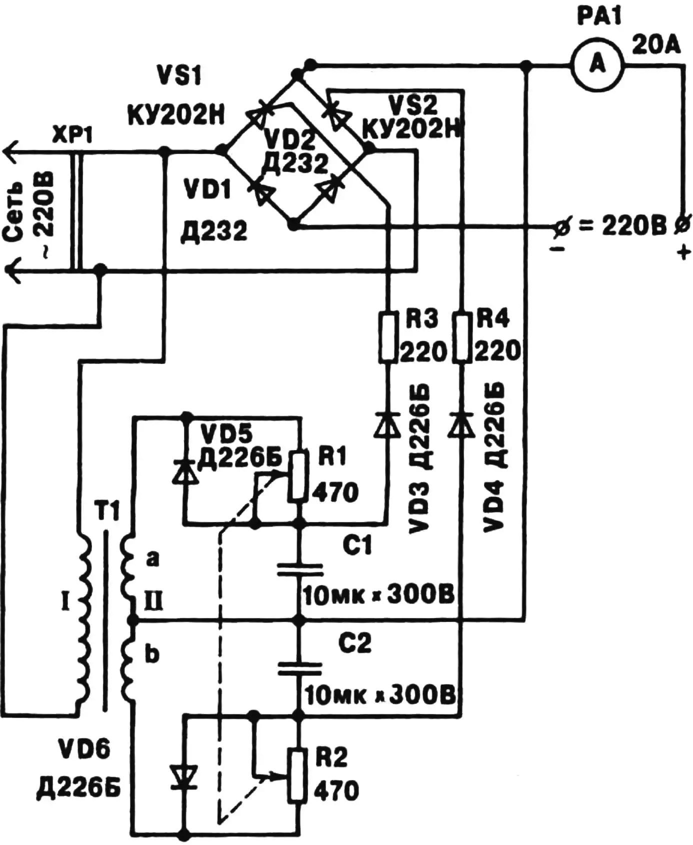
One more detail. Although the power supply (see Fig. 4) can feed a 3.4 kW load, such high power is very rarely needed in amateur practice. And to avoid “running the electronics” almost idle (in half-wave rectification mode, when the output is 0…1.7 kW), it is useful to have another, smaller and simpler electrolyzer power source (Fig. 5). In essence, this is a full-wave adjustable rectifier familiar to many DIY enthusiasts, with the “sliders” of the 470-ohm potentiometers mechanically coupled. Structurally, such coupling can be made either with a simple gear drive using two textolite gears, or with a more complex vernier-type device (as in a household radio receiver).
The transformer in the power supply is homemade. An Sh16x32 stack of transformer steel is used as the magnetic core. The windings contain: primary — 2000 turns of PEL-0.1; secondary — 2×220 turns of PEL-0.3.
Practice shows that the homemade gas cutting and welding apparatus described here can serve reliably for a very long time even under the most intensive use. True, thorough maintenance is required about once every 10 years, mainly because of the electrolyzer. Its plates, working in an aggressive medium, become coated with iron oxide, which begins to act as an insulator. The plates have to be washed and then cleaned on a grinding wheel. Moreover, four of them (at the negative pole), eaten away by acid residues collecting near the “minus,” have to be replaced.
Therefore it is recommended to fill the electrolyzer only with distilled water and to use an alkali solution as free of salts as possible (traces of sulfuric and hydrochloric acid compounds are unacceptable).
The use of so-called drain holes (in addition to the filler and gas-outlet openings) can hardly be considered justified either, and this was taken into account when developing the apparatus. Equally unnecessary is adding cans to the apparatus for collecting the accumulating highly aggressive alkali. Moreover, operation of the “can-free” design shows that over a 10-year period no more than half a glass of this “harmful liquid” collects at the bottom of the kerosene seal. The accumulated alkali is removed (for example, during maintenance), and a fresh portion of clean kerosene is poured into the seal.
Modelist-Konstruktor No. 3’97, V. RADKOV, Tatarstan
Recommend to read
 LION OF THE DESERT
Israeli fighter "Kfir". In 1967 the French President Charles de Gaulle banned the supply of arms to Israel. This decision was a response to the Israeli attack on the neighboring Arab... NO WORSE THAN FACTORY
Brush motor run relatively short. And if not in stock new, home "helper" comes the forced inaction. Meanwhile, a new brush it is easy to make from coal cores extracted from the...
