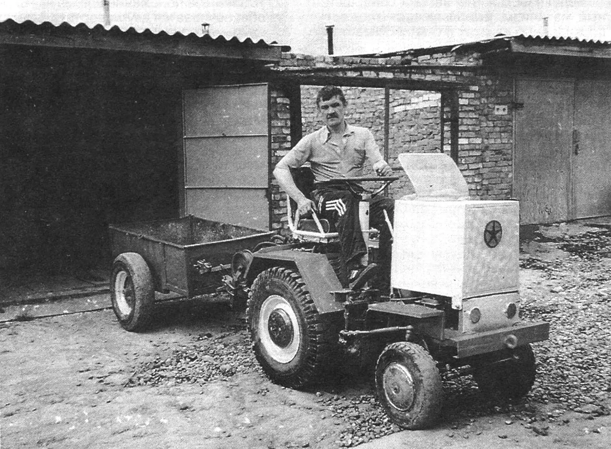
This mini tractor was built by Y.V. Polyabin, a self-taught designer, from whatever he could find in his own garage, from acquaintances, and at a scrap yard. Nevertheless, “Krokha” (as he named his mini tractor) holds a privileged place in the craftsman’s spacious garage. Even though a “Kuzya” jeep and a “Kolibri” mini-car stand next to it, this mechanical workhorse gets technical maintenance first and repairs in the shortest possible time. And how could it be otherwise? “Krokha” is truly the breadwinner of its creator’s family! Without it, you cannot prepare the garden for planting potatoes or harvest the crop.
As usual, the tractor’s design is based on units from various cars and agricultural machines that had already served their time. The designer managed to arrange them quite compactly in a small volume, which is why the machine quite deservedly received the “mini” prefix in its name.
The “Krokha” layout is classic; the author did not overcomplicate anything and followed the principle: the simpler, the better. This approach proved itself: the mini tractor is easy to maintain and easy to drive. In the photo and in the layout drawing, it is shown with the hood installed. However, in the field Yuriy Viktorovich prefers to remove the hood: the rows are easier to see, and the engine cools more intensively.
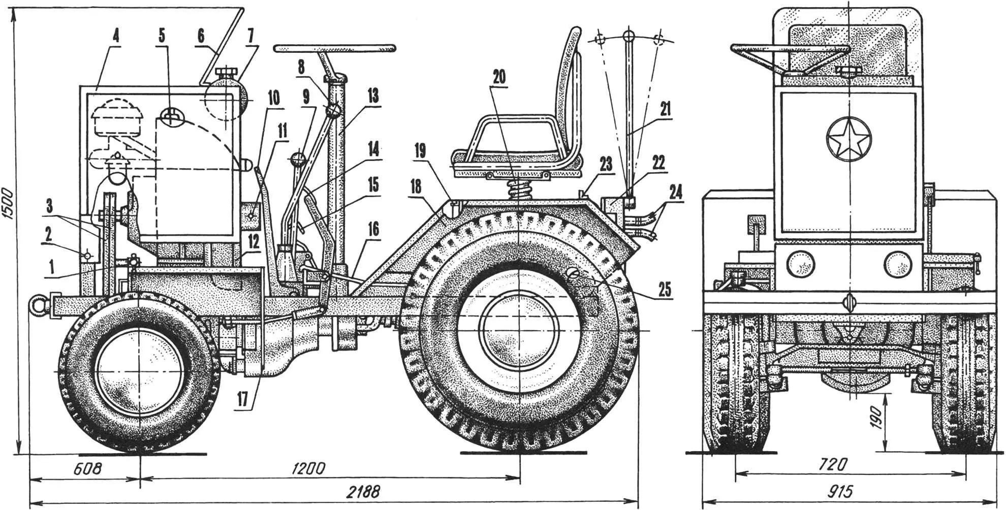
1 — drive belt tensioner; 2 — hood hinge axis; 3 — drive belts; 4 — hood; 5 — ZID-4.5 engine; 6 — wind shield; 7 — fuel tank; 8 — gearshift lever;
9 — PTO gearbox control lever; 10 — parking brake lever; 11 — starting shaft; 12 — hood support (20×20 angle, 2 pcs.); 13 — steering column; 14 — clutch pedal; 15 — throttle pedal; 16 — floor; 17 — front fender splash guard; 18 — rear fender; 19, 23 — crosspieces (20×20 angle); 20 — telescopic spring-loaded seat post; 21 — hydraulic spool control lever; 22 — three-position spool unit; 24 — hydraulic hoses; 25 — hydraulic tank.
“Krokha” has to work a lot. The Lotoshino soil is not the easiest, and the owner’s garden is not small either, so there is always something to do: plowing, harrowing, cultivating. Neighbors also ask for help—how can you refuse? In short, the load on every shaft and every bolt is serious. But “Krokha” works flawlessly. Such reliability can be explained, first, by the thoughtful and competent selection of all units and assemblies, and second, by careful, masterful fabrication. No wonder Y.V. Polyabin is skilled in more than twenty professions!
One of those professions—welding—was especially useful when making the mini tractor frame. The frame is a rectangular structure welded mainly from channels and angle sections of various profiles. Almost all transmission units are attached to it from below, from the intermediate shaft housing to the rear axle. On top are the engine, controls, driver’s seat, fenders, and part of the hydraulic system units. At the front, the frame has a towing eye bolt; at the rear, a hitch for a trailer and mounted equipment.
The tractor uses a ZID-4.5 engine. It is a stationary, single-cylinder, two-valve engine rated at 4.5 hp at 2600 rpm, with an internal two-speed gearbox (low and high range), and it runs well on A-72 or A-76 gasoline. It is installed with the output shaft facing forward in the direction of travel and mounted on two brackets with four bolts. Therefore, the starting shaft ended up at the rear, close to the driver, which allows the engine to be started without getting up (it is stopped simply by turning the carburetor air damper).
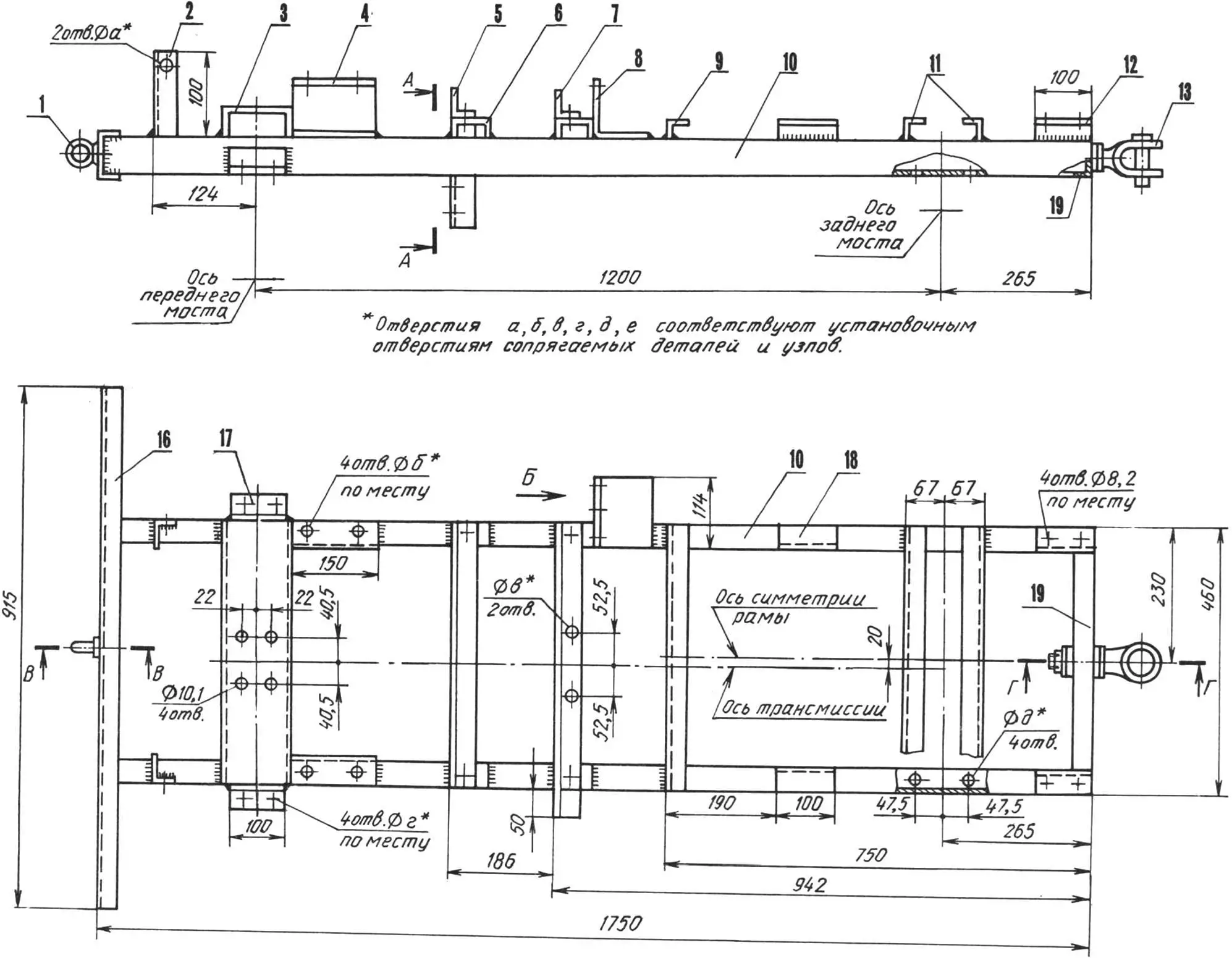
1 — towing eye bolt; 2 — hood hinge post (40×40 angle, 2 pcs.); 3 — intermediate transmission shaft mounting beam (120×52 channel); 4 — engine support (100×46 channel, 2 pcs.); 5, 7 — front and rear gearbox crossmembers (50×50 angle); 6 — spacer (65×36 channel, 4 pcs.); 8 — steering mechanism mounting bracket (100×100 angle); 9 — front floor support (32×32 angle); 10 — frame rails (65×36 channel); 11 — rear floor supports (32×32 angle); 12 — hydraulic tank support (32×32 angle, 2 pcs.); 13 — hitch; 14 — gearbox mounting brackets (50×50 angle); 15 — bracket reinforcement (25×5 strip); 16 — bumper (32×32 angle); 17 — front axle beam mounting bracket (45×45 angle, 2 pcs.); 18 — side floor support (32×32 angle, 2 pcs.); 19 — crossmember (65×36 channel); 20 — reinforcing plate (steel sheet s5); 21 — power bushing.
The 150 mm dual-groove pulley on the output shaft is connected by A1060 belts (from a GAZ-51 truck) to a 190 mm pulley on the intermediate transmission shaft. Thus, the 15:19 belt ratio provides 2000—2100 rpm, which is quite acceptable for the main gearbox. Belt tension is adjusted by a dedicated mechanism located on the left front wheel fender.
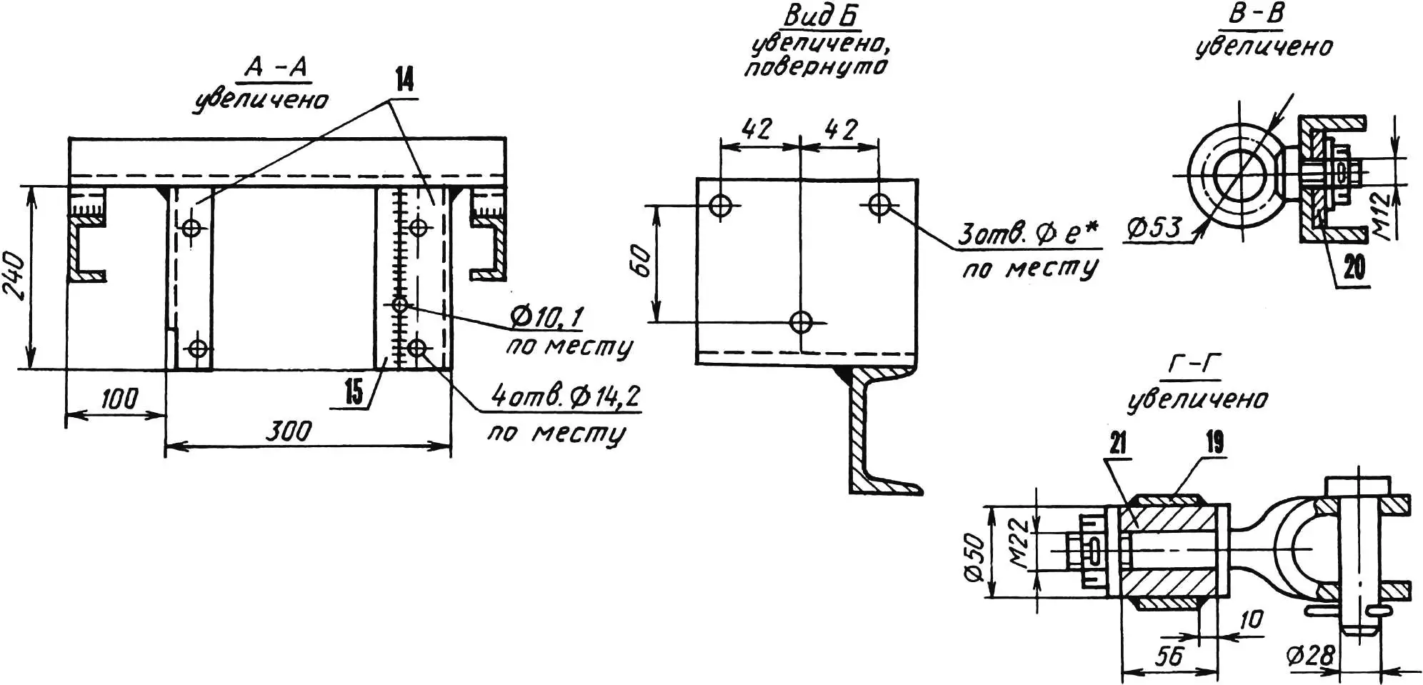
The 32 mm intermediate shaft rotates in two ball bearings installed in a cylindrical housing, which is bolted with four bolts to the frame beam from below. The design is generally simple and requires no special explanation.
A flange cut from a GAZ-51 crankshaft is welded to the rear end of the intermediate shaft. The engine flywheel (without ring gear) and a UAZ-469 clutch basket are attached to the flange with four M12x1.25 bolts. The clutch actuator lever is placed in the space between the clutch basket and gearbox and mounted on the left gearbox bracket (for this, the bracket is reinforced with a welded steel plate into which the lever pivot axis—an M10 bolt—is inserted). A rod with eyelets at both ends connects the lever to the clutch pedal under the driver’s left foot.
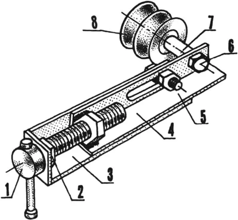
1 — M16 hand screw; 2 — M16 locknut; 3 — housing (28x28x3 angle); 4 — slider (25x25x3 angle); 5 — retainer (M12 bolt); 6 — M12 roller axle bolt; 7 — roller axle; 8 — dual-groove roller.
The gearbox is from a GAZ-51 vehicle, with four forward gears and one reverse. Six holes in the rear crossmember and vertical frame brackets are provided for mounting the gearbox. The gearshift lever and parking brake handle are routed upward between the crossmembers.
Using a homemade driveshaft welded from UAZ-469 and GAZ-24 shafts, the gearbox is connected to the mini tractor’s rear axle (from a GAZ-24 Volga car). (It should be noted that due to the offset of the final drive pinion in the rear axle, the transmission longitudinal axis is located 20 mm to the left of the frame’s longitudinal symmetry axis.)
Since the Volga wheel track is wider, the axle housings and axle shafts were shortened. The modification technology was as follows. The housings were cut closer to the wheel flanges and shortened to the required length; cut areas were centered on a lathe, tack-welded at three points, then fully welded around the circumference at low spindle speed and left clamped until fully cooled.
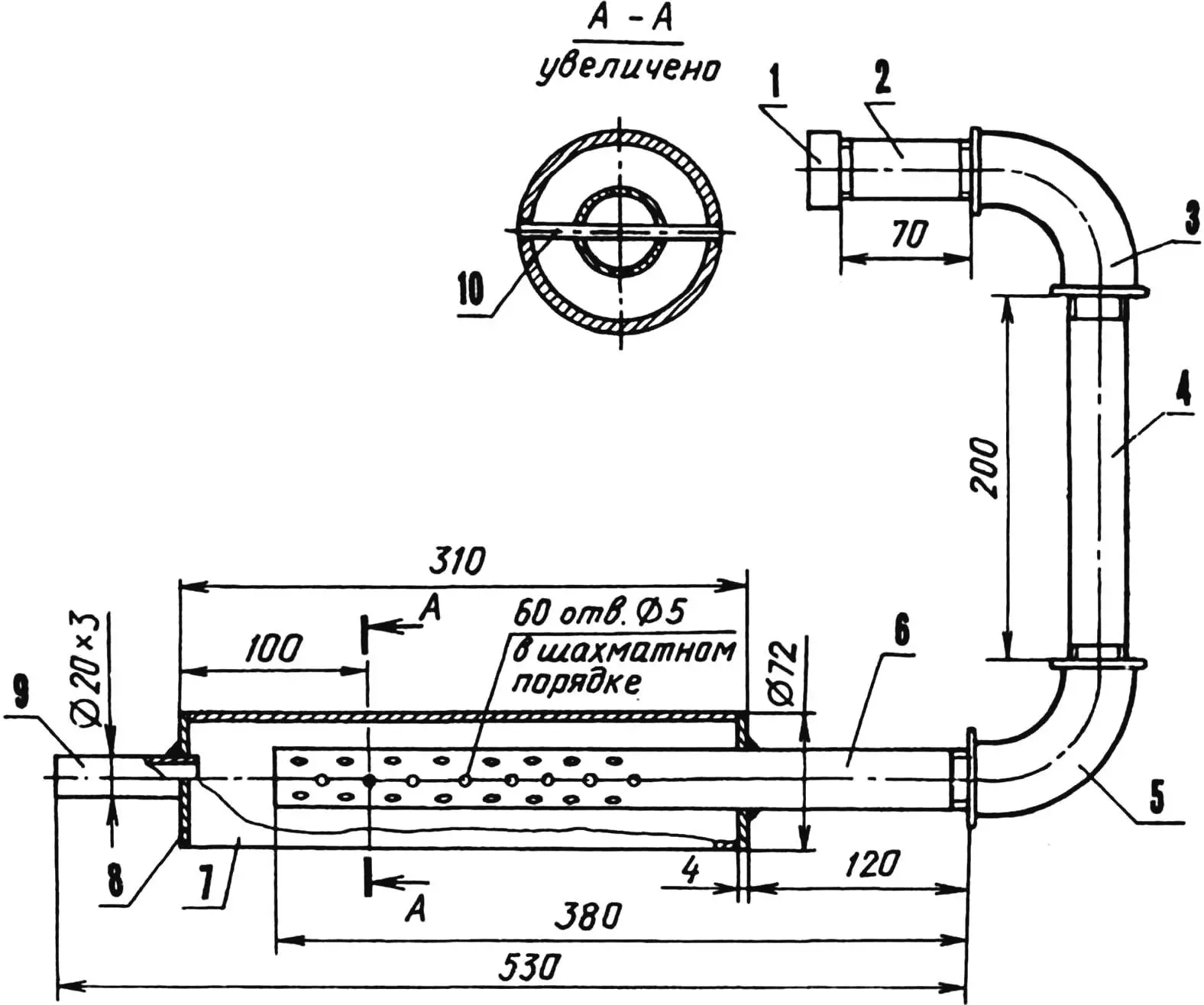
1 — inlet flange (shortened plumbing coupling); 2,4,6 — exhaust pipe sections (32×3 pipe); 3,5 — elbows; 7 — resonator (GAZ-24 driveshaft tube); 8 — end plates (steel, sheet s4, 2 pcs.); 9 — outlet pipe; 10 — retainer (rod Ø5).
The axle shafts were modified in a similar way. Only before the three-point tacking, they were joined by M16 studs screwed into axial threaded holes drilled in the centered ends. They also cooled on the lathe. It should be added that the axle hubs are UAZ type, since the rear wheels of “Krokha” are also from a UAZ-469 (size 8.40—15”).
The rear axle is attached to the lower flanges of the frame side members by its support pads using four bolts. The shackles welded to the axle housings below the support pads were moved closer to the mini tractor’s centerline to attach the mounted implement linkage to them.
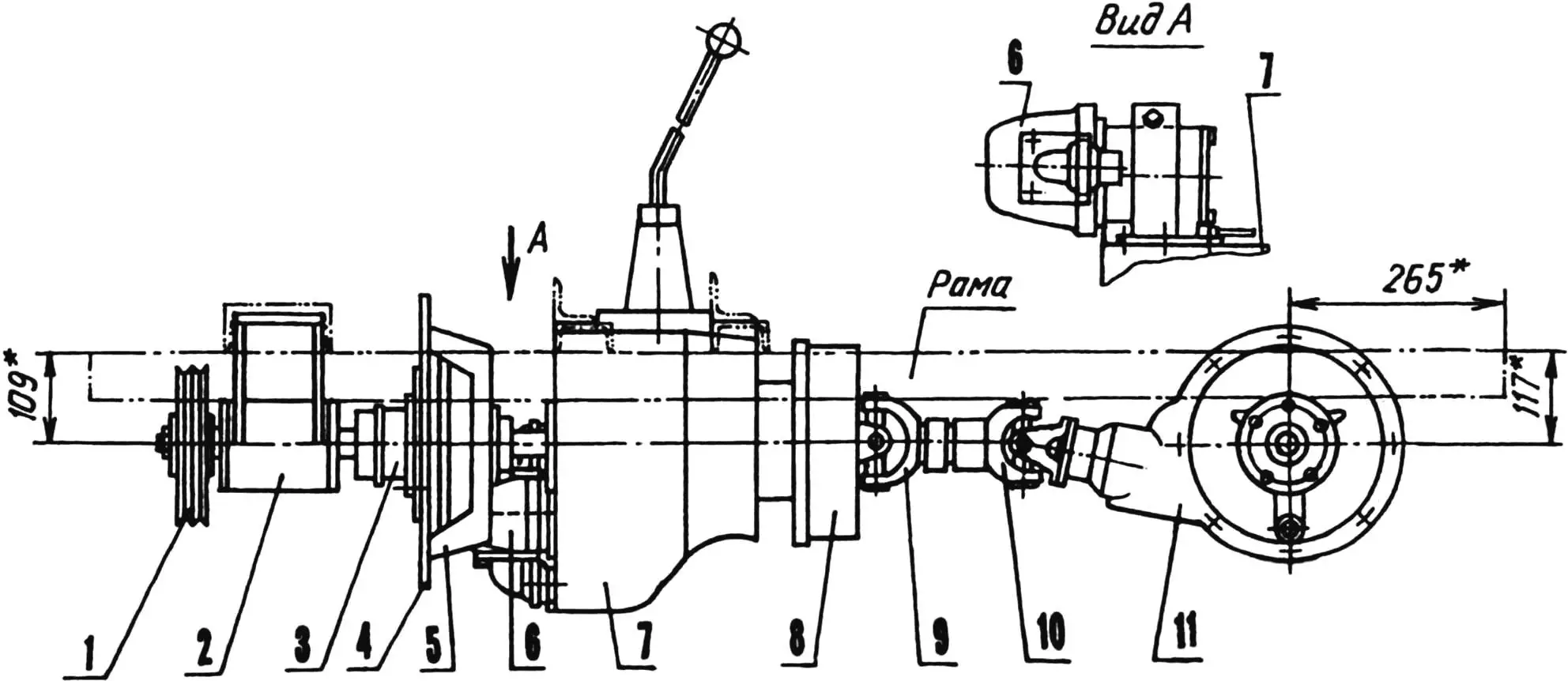
1 — intermediate shaft pulley (Ø190); 2 — intermediate shaft bearing housing; 3 — flange (from GAZ-51 crankshaft); 4, 5 — engine flywheel (without ring gear) and clutch basket (from UAZ-469); 6 — NSH-50 hydraulic pump with PTO gearbox (suction/discharge hoses and gearbox engagement lever are not shown conventionally); 7 — gearbox (from GAZ-51); 8 — parking brake drum (brake handle and its drive are not shown conventionally); 9 — front driveshaft yoke (from UAZ-469); 10 — rear driveshaft yoke (from GAZ-51); 11 — rear axle (from GAZ-24).
This transmission provides the mini tractor with working speeds in the range from 5 to 20 km/h.
The front axle design also uses parts and assemblies from other machines. Wheels sized 5.0—10”, for example, were taken from an agricultural machine (mechanical rake). And as a base, the beam of a forklift’s rear (steered) axle was used. A thick-walled suspension bushing and two reinforcing plates were welded to it.
A suspension bracket (a yoke from a UAZ-469 driveshaft) is connected to that bushing by a kingpin and thick brass washers. The bracket is bolted with four bolts to the intermediate front axle beam, which will be discussed next.
The steering knuckles are from a GAZ-24. Slightly modified steering linkage arms from a Moskvich-407 are screwed in from below, while from above—only to the right knuckle!—a steering bracket is welded. It is made of channel section with a bent top part without flanges. A shortened steering arm from a Moskvich-412 is welded to it and connected by a rod to the pitman arm of the steering gear. The steering gear, also from a Moskvich-412, is mounted on the frame on the right side in the direction of travel and attached by three bolts to a special bracket. The steering column is slightly shortened.
A longitudinal tie rod from a UAZ-469 is used as the cross tie rod of the steering linkage. It is shortened and equipped with a hex insert for a 19 mm wrench for easier toe/camber adjustment.
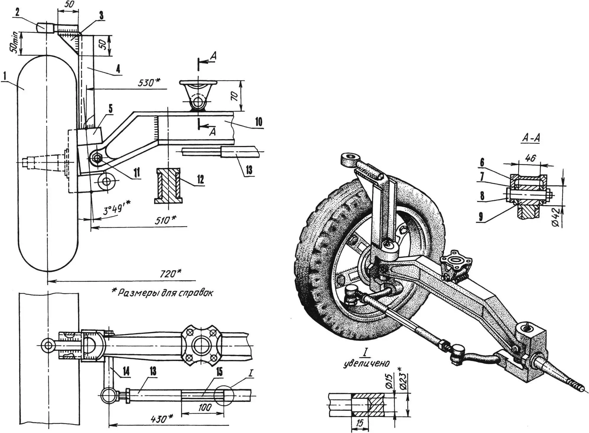
1 — wheel (from mechanical rake, 2 pcs.); 2 — steering arm (from Moskvich-412); 3 — stiffening rib (steel, sheet s5, 2 pcs.); 4 — steering bracket (65×36 channel); 5 — steering knuckle (from GAZ-24, 2 pcs.); 6 — suspension bracket (from UAZ-469 driveshaft); 7 — washer (brass, 2 pcs.); 8 — kingpin with M14 thread; 9 — axle suspension bushing; 10 — axle beam (from forklift rear axle); 11 — locking bolt (2 pcs.); 12 — reinforcing plate (steel, sheet s10, 2 pcs.); 13 — cross tie rod (shortened UAZ-469 longitudinal tie rod); 14 — steering linkage arm (2 pcs., not shown conventionally in front view); 15 — hex insert for 19 wrench.
The front axle is connected to the mini tractor frame by an intermediate beam made of a channel and two angle sections. The advantage of this mounting method is that if the axle must be removed for repair, there is no need to crawl under the tractor and unscrew the suspension bracket.
It is enough to bend down slightly and unscrew four bolts on the intermediate beam, then grab the bumper and move “Krokha” to the side—the axle will be right in front of you.
The engine hood is welded from three 1.2 mm steel sheets and a ventilation mesh (at the front). Before welding, the sheet edges were flanged.
The front and rear fenders are made of the same metal.
1 — bracket (45x45x5 angle, 2 pcs.); 2 — beam (100x46x7 channel).
For the floor, a thicker steel sheet was used—5 mm—and attached with self-tapping screws to three transverse and four longitudinal supports made of 32×32 mm angle, welded to the frame side members.
1 — front crosspiece (20×20 angle); 2 — stiffening rib (20×20 angle); 3 — fender; 4 — fender bracket (32×32 angle); 5 — floor (steel, sheet s5); 6 — side floor support (32×32 angle); 7 — side member (65×36 channel).
The driver’s seat is installed on the floor (above the rear supports), equipped with a telescopic spring-loaded post. The seat frame is made of 20 mm pipe. The cushions are made of plywood, foam rubber, and leatherette. The post consists of two pipes: upper (40 mm diameter) and lower (50 mm diameter). The first is welded to the seat frame, the second to the floor. Two springs twisted together from Moskvich-2141 front suspension are fitted on them to balance the driver’s weight.
To work with interchangeable farm implements, the mini tractor has a hydraulic system and a mounted linkage.
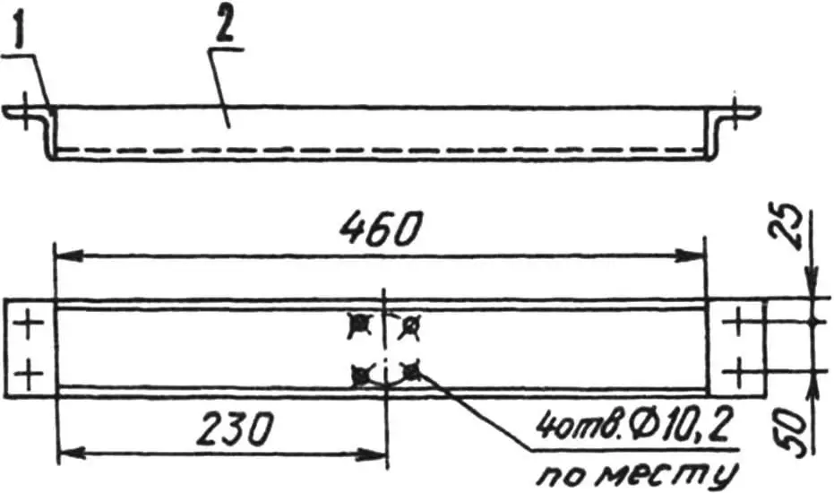
1 — support (25×25 angle, 2 pcs.); 2 — bottom (steel, sheet s6, 2 pcs.); 3 — tank body (100×5 pipe); 4 — outlet fitting (20×3 pipe); 5 — inlet fitting; 6 — siphon body; 7 — siphon; 8 — plug.
The hydraulic system includes a PTO gearbox (located on the right side of the gearbox), an NSH-50 pump (same place), a tank (on dedicated supports at the rear of the frame), a three-position spool unit (on the left bracket of the power cylinder), the power cylinder itself, and hoses.
The mounted linkage consists of two beams—rectangular-section tubes welded from 50×50 angle. The front ends of the beams are coupled to shackles under the rear axle, and the rear ends are connected to interchangeable farm implements via a “square” connector. Approximately in the middle, a crossbar for the power cylinder rod is attached to the beams. All joints in the mounted linkage are intentionally made with clearances. This is done so that the structure does not jam even under significant misalignment and vibrations inevitable during operation of a plow, harrow, hiller, or cultivator.
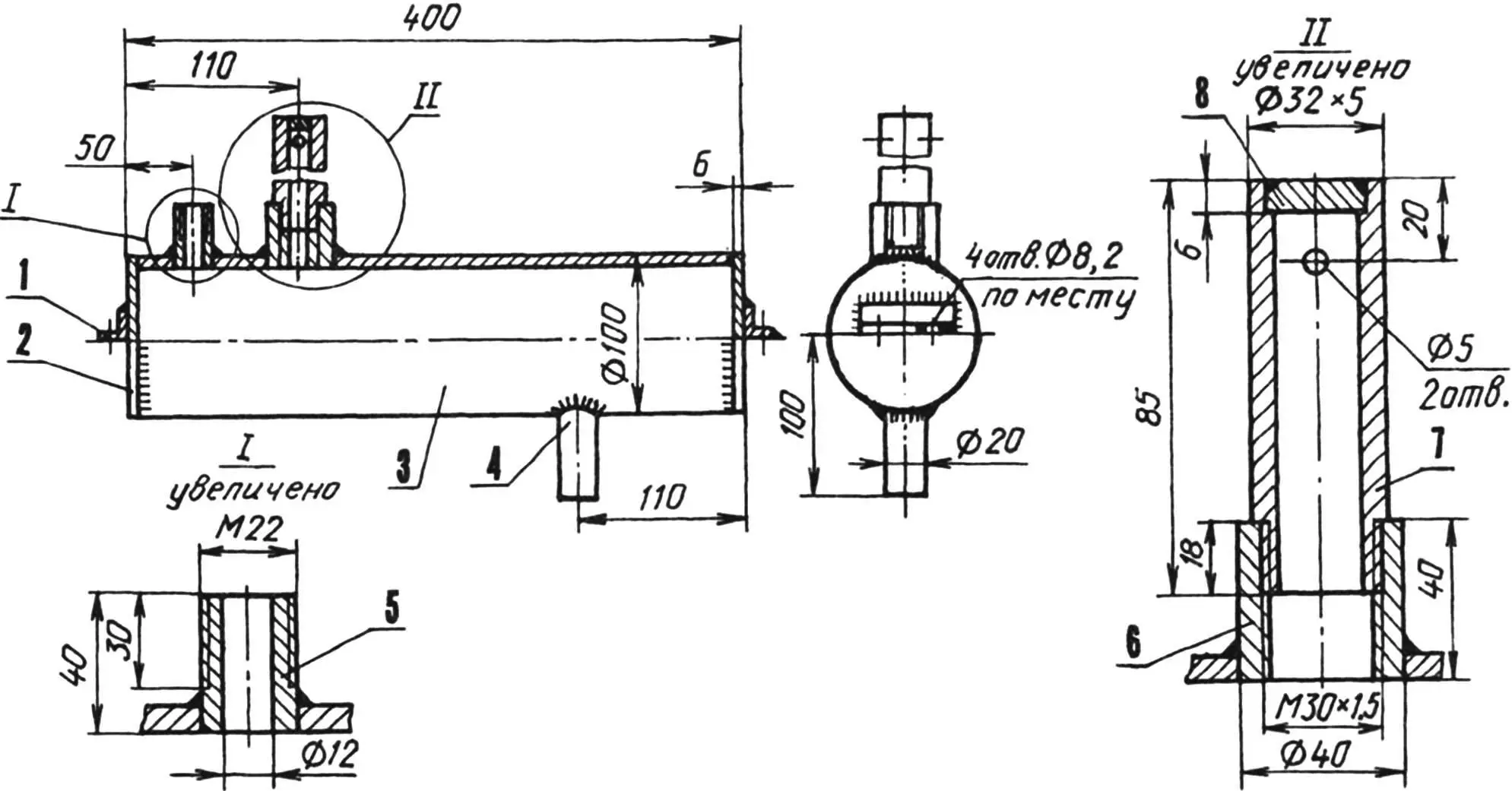
1 — beam (50×50 angle, 2 pcs.); 2 — “square” seat (from agricultural machine, 2 pcs.); 3 — U-bolt (2 pcs.); 4 — “square” bar (28×28 rod); 5 — lower spacer bushing (48×4 pipe, 2 pcs.); 6 — power cylinder (from agricultural machine); 7 — cylinder bracket (50×50 angle, 2 pcs.); 8 — upper spacer bushing (30×2.5 pipe, 2 pcs.); 9 — mini tractor frame; 10 — cylinder crossbar (Ø20 rod); 11 — M20x1.5 nut (2 pcs.); 12 — power bushing (40×3 pipe, 2 pcs.); 13 — cylinder rod crossbar (Ø24 rod); 14 — M24x1.5 nut (2 pcs.); 15 — M16 nut (4 pcs.).
Naturally, the mini tractor’s “arsenal” also includes a cargo trailer. What harvest work is possible without it? The trailer is hitched to the frame crossmember hitch and can carry over 300 kilograms of potatoes in its bed. And “Krokha’s” pulling capability is such that it can transport loads weighing up to one ton.
“Modelist-Konstruktor” No. 7’98, A. TYMCHENKO
Recommend to read
 MAGICAL TRANSFORMATIONS OF PAPER
His appearance in the editorial was met with a, frankly, no enthusiasm; preliminary telephone conversation were no signs, it seemed, nothing sverhinteresnogo. Homemade paper? Well,...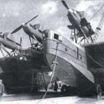 “ALBATROSS” OF THE 1930S
The weakness of the Navy of the USSR in the prewar years, tried to compensate by creating flying cruisers - multi-engined and heavily armed seaplane, able to deal with both surface and...
