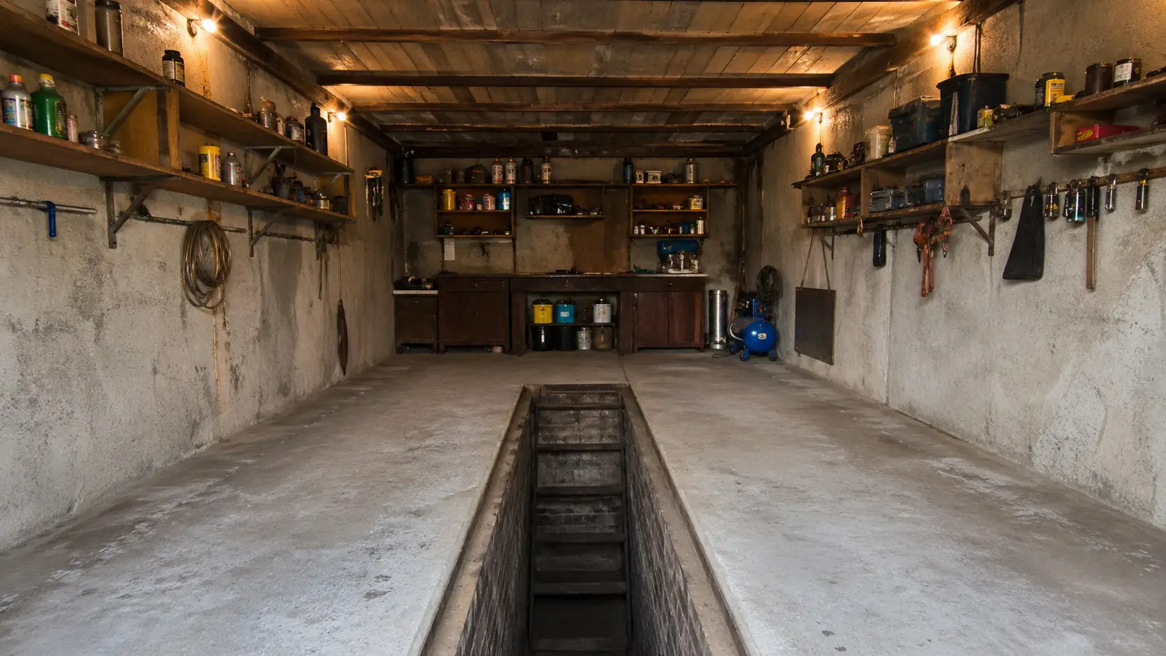
A garage for a car enthusiast is not only a roof over the car but also a place where you spend quite a lot of time yourself: you need to touch up the body, change the oil, or even tackle serious repairs. That is why rational planning of the space and sensible organization of the work area matter to most owners of covered parking garages. This topic has already been discussed in the magazine. Thus, in No. 2 for 1987, an article by A. Lazarev was published on using a manual hoist in repair work. Today the editorial office returns to this topic and offers readers an article by A. Godyna.
When planning a garage before construction, you need to allow for repair work, including engine removal. Therefore it is best to keep the garage floor clear, while auxiliary equipment, shelves, and cabinets with spare parts, materials, and tools are better placed on the walls or suspended from the ceiling.
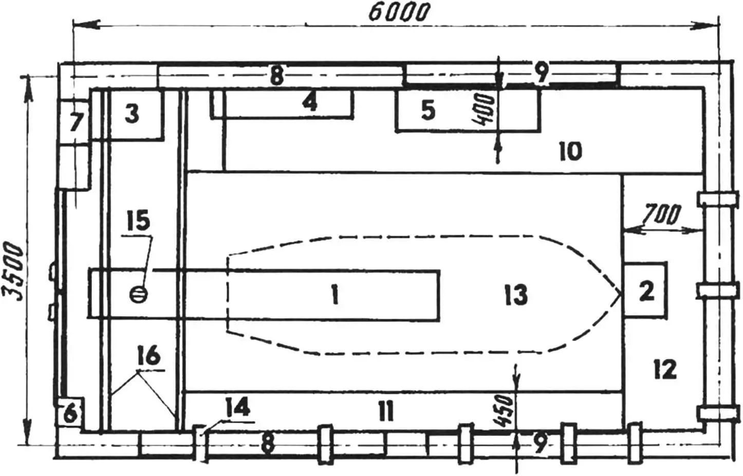
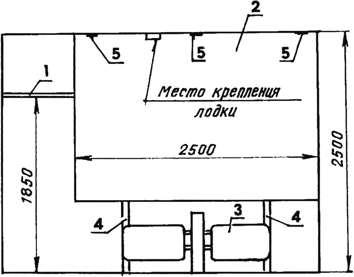
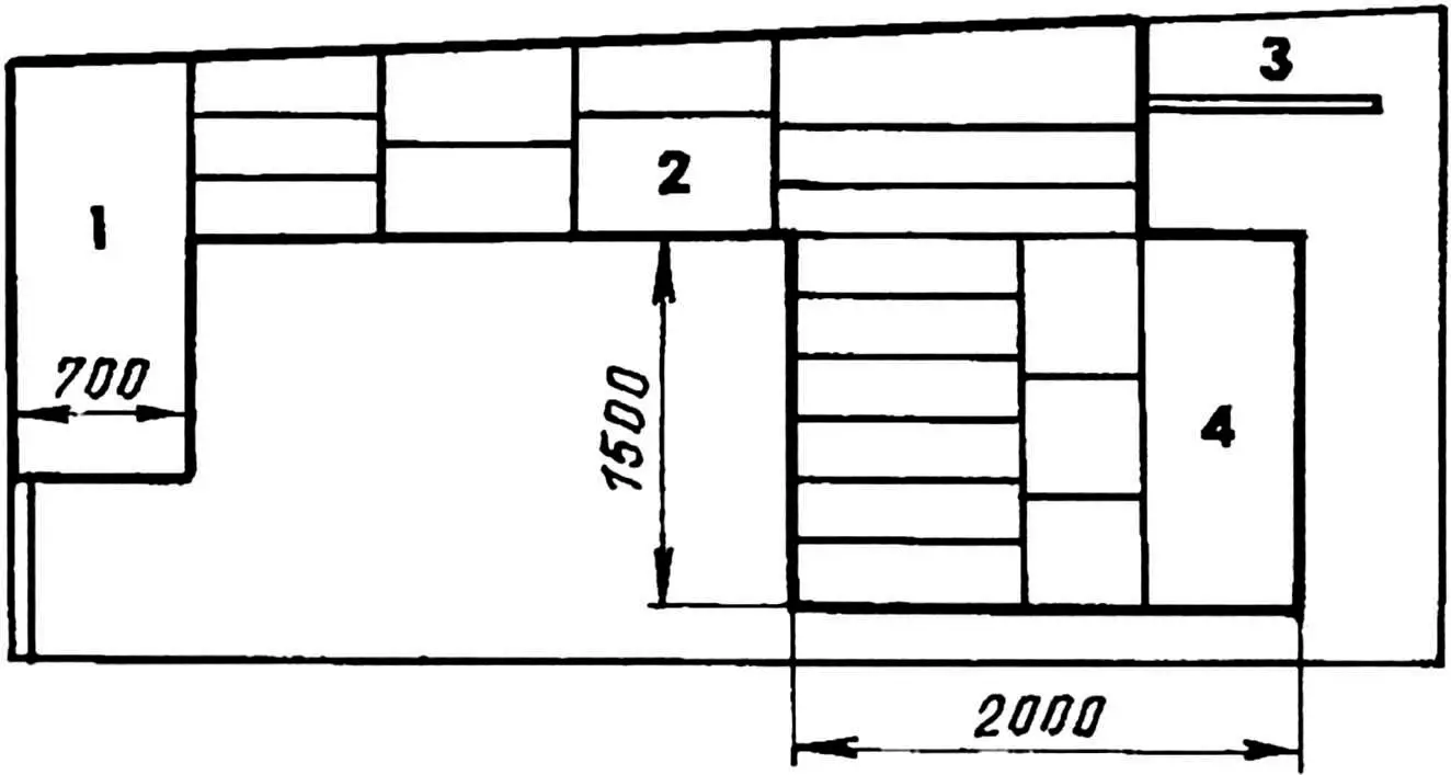
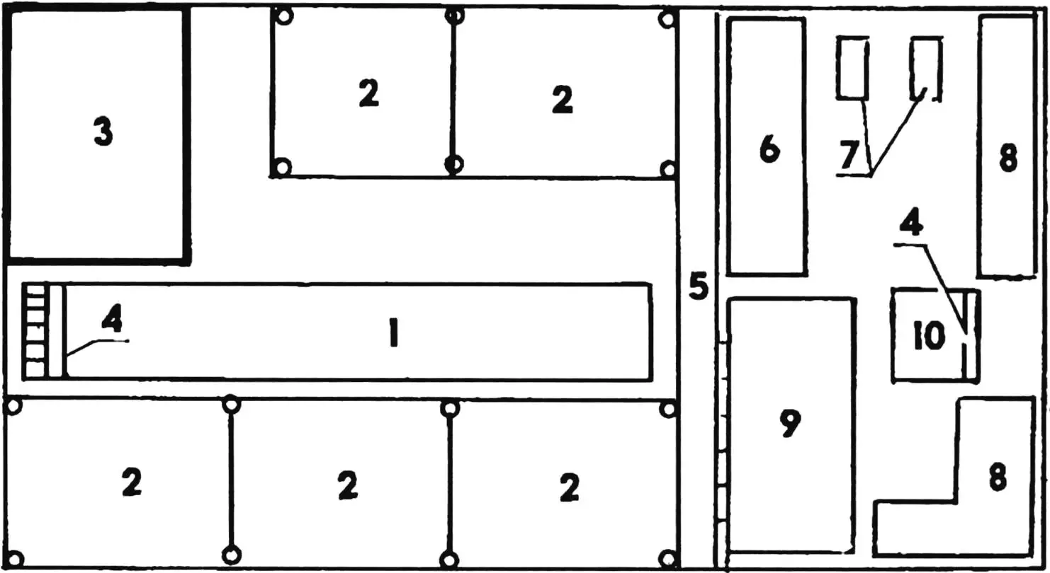
1 — inspection pit; 2 — cellar hatch; 3 — workbench; 4 — rack with equipment; 5 — tool cabinet; 6, 7 — ventilation ducts; 8 — niches opening into the garage; 9 — niches opening toward neighbors; 10 — shelf for wheels; 11 — small wall cabinet; 12 — large wall cabinet; 13 — boat storage under the ceiling; 14 — embedded plate for welding (8 pcs.); 15 — eye bolt; 16 — travel rails (steel angles 75×75×8 mm, 2 pcs.)
Figure 1 schematically shows a garage plan with rational use of the interior space. Most noticeable is the gate shifted to the right to widen the free floor area on the left, as well as replacing part of each side brick wall with two niches made as welded frames from channel sections and covered with sheet steel. By agreement with the adjacent garage neighbor, one of the two niches opens to the owner and the second to the neighbor.
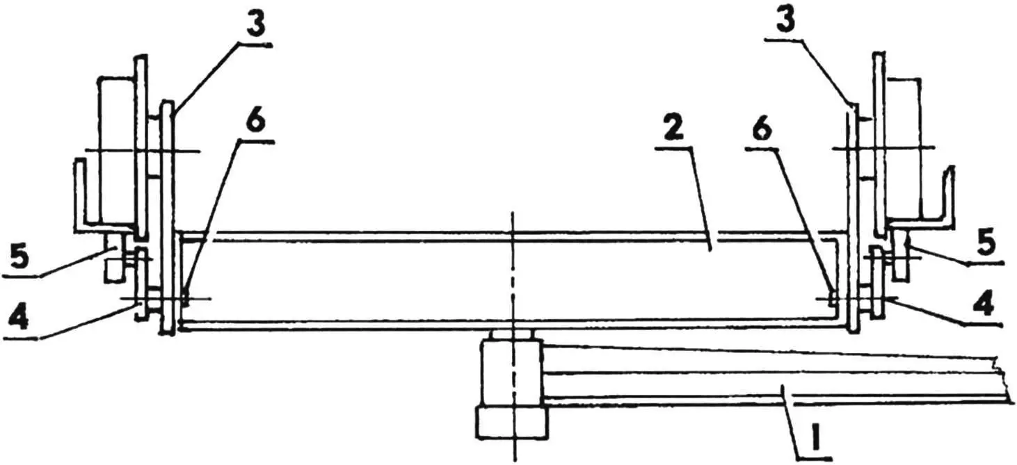
1 — cantilever (manual hoists not shown); 2 — trolley frame; 3 — wheel blocks from hoists (4 pcs.); 4 — brackets (4 pcs.); 5 — rollers (4 pcs.); 6 — bolts M14×40 (8 pcs.)
According to the design, above the gate opening the garage has a shelf made of two steel angles 75×75×8 mm (item 16 in Fig. 1), built into the side walls. Here it is possible to mount a trolley (Fig. 2) with a cantilever on the angles instead of the shelf; manual hoists are installed on the cantilever, as suggested by A. Lazarev (“Modelist-Konstruktor”, No. 2 for 1987).
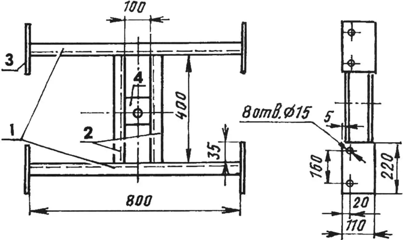
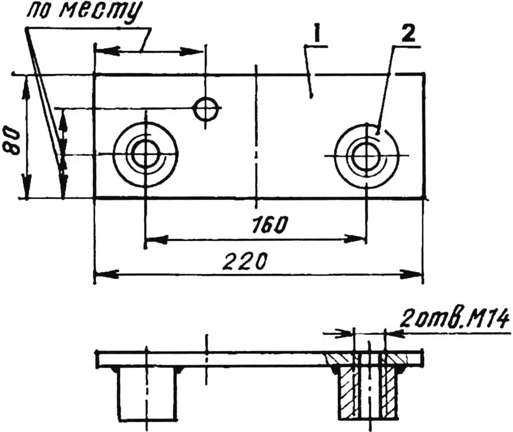
1 — cross beams (channel No. 10, L800); 2 — longitudinal beams (channel No. 10, L400); 3 — flange (steel, sheet s12, 4 pcs); 4 — support plate (steel, sheet s30; 100×100)
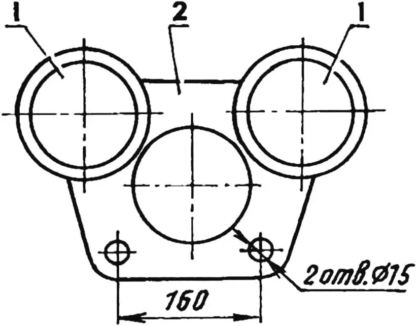
1 — wheels assembled (2 pcs); 2 — housing
1 — plate (steel, sheet s12); 2 — boss (steel, round bar Ø40, 2 pcs.)
The trolley is a frame (Fig. 3) welded from steel channel No. 10. A 100×100×30 mm plate with a hole for mounting the cantilever swivel unit is welded in the center of the frame. Four flanges with holes for attaching wheel blocks (from decommissioned hoists) and brackets are welded at the frame edges; one roller is mounted on each bracket. The rollers contact the underside of the angle shelf and prevent the trolley from tipping.
Wall cabinets and shelves in the garage are welded to embedded plates installed during construction. Figure 8 shows one such plate.
1 — shelf for wheels; 2 — wall cabinet for belongings; 3 — oil electric heater; 4 — uprights (channel No. 10, 2 pcs.); 5 — embedded plates
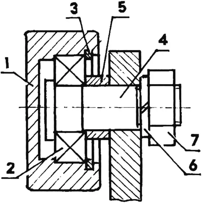
1 — roller; 2 — ball bearing; 3 — retaining ring; 4 — shaft; 5 — bushing; 6 — spring washer; 7 — nut
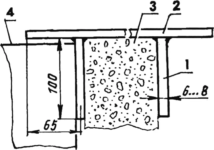
1 — longitudinal plate (steel, sheet s8; 100×100, 2 pcs.); 2 — transverse plate (steel, sheet s8; 100×130, 2 pcs.);
3 — wall; 4 — wall cabinet
Garage outfitting is shown in the figures. Against the rear wall (Fig. 6) there is a shelf for wheels; a cabinet for belongings is mounted on the wall. The lower edge of the cabinet should be at least 100 mm above the car hood and trunk. Below the cabinet it makes sense to install a thin electric heating device. Equipment placement at the right and left walls is shown in Figs. 9 and 10 respectively, and the front wall with the gate — in Fig. 11. The basement (Fig. 12), besides garage functions (inspection pit, material racks), also serves household needs: vegetable storage and even mushroom growing.
1 — wall cabinet; 2 — small wall cabinet; 3 — cross shelf; 4 — niche (built-in cabinet)
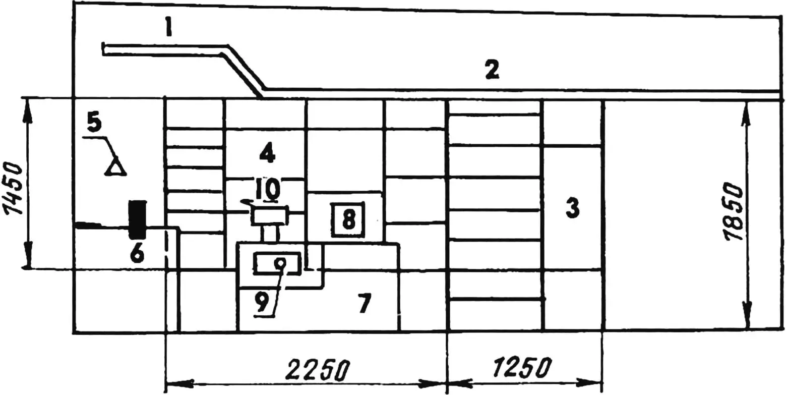
1 — cross shelf; 2 — shelf for wheels; 3 — tool cabinet (also support for shelf item 2); 4 — niche (built-in cabinet); 5 — bracket-mounted lamp; 6 — workbench; 7 — equipment rack; 8 — charging unit; 9 — welding machine; 10 — bench grinder
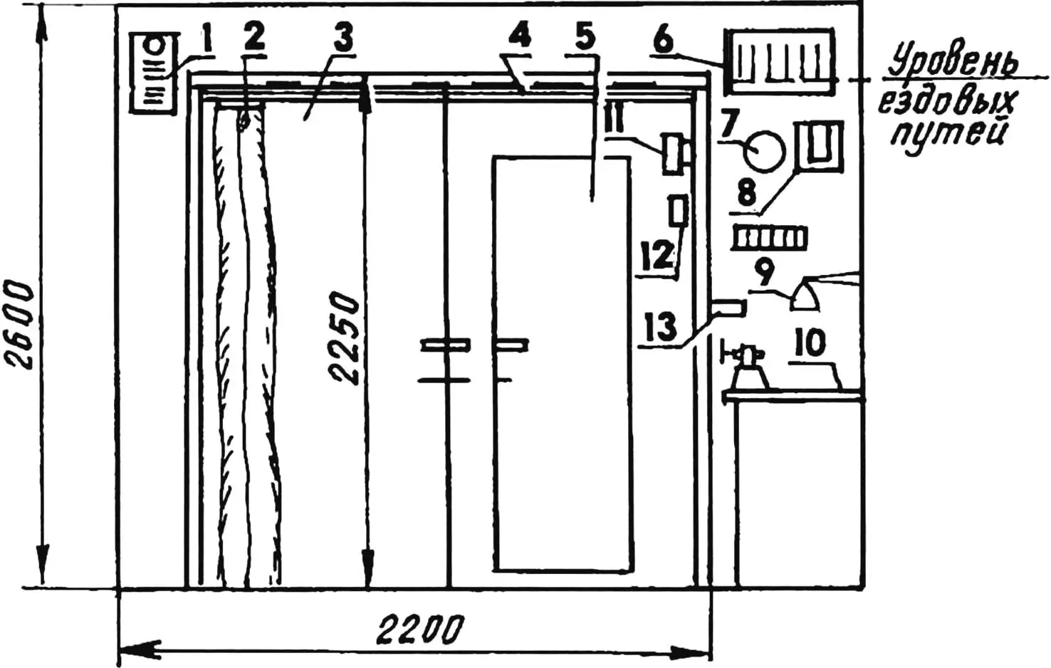
1 — ventilation duct; 2 — curtain; 3 — gate; 4 — cornice; 5 — door; 6 — ventilation duct with door; 7 — wall lamp; 8 — electrical panel; 9 — bracket-mounted lamp; 10 — workbench; 11 — fire extinguisher; 12 — first-aid kit; 13 — shelf for keys
1 — inspection pit; 2 — racks; 3 — mushroom-growing platform; 4 — cellar doors (hatches); 5 — partition wall; 6 — canned goods rack; 7 — vegetable storage in baskets; 8 — canned goods racks; 9 — potato bin; 10 — cellar hatch
Of course, every motorist has their own garage layout, car service needs, and household requirements — but something described here may still prove useful.
From the editors
Under general occupational safety rules, lifting equipment (here, a trolley with a manual hoist) must have a brake or locking device. The simplest lock is removable wheel chocks placed under the trolley wheels. Note also that using four pairs of wheels from hoists is impractical; four wheels on the frame are enough.
“Modelist-Konstruktor” No. 11’2005, A. GODYNA
Recommend to read
 ACROSS THE FIELD SWEEPING PLOUGH
We offer our readers the plow rather unusual. It is not necessary to pull forward, neither a horse nor a tractor, and the now familiar motor-plow is selhozgodu clearly does not. It has... Tracked… motorcycle
The design presented here is a half-track motorcycle with a steering front wheel on a low-pressure tire and a driven track, intended for off-road travel—mainly in summer and in the...
