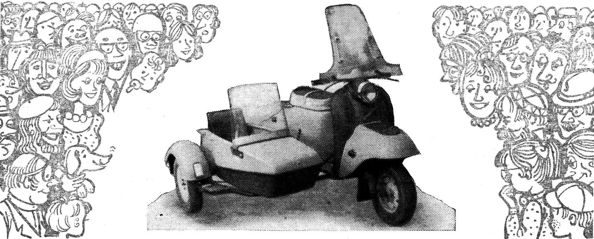
Enthusiasts build sidecars for all kinds of motorcycles and motor scooters! For Izh and Voskhod, for old Zündapps and brand-new Vyatka-Elektron. Owners of Tula-200 motor scooters are also happy to add a third wheel to their machine — especially since the engine power of the modern Tula-Tourist makes it quite feasible. Unlike many such trailers, the design proposed by Vladimir Kovalev from Bryansk stands out with bold styling, a strict match of its contours to the motor scooter’s shape, reliability, and modern fiberglass body technology. So: a sidecar for the Tula-Tourist.
The sidecar body is made of fiberglass (two layers of glass mat on epoxy resin).
It consists of two halves formed in a single mold made of plywood (hardboard) and strips. The joint areas are rounded with strips, and irregularities are filled with modeling clay.
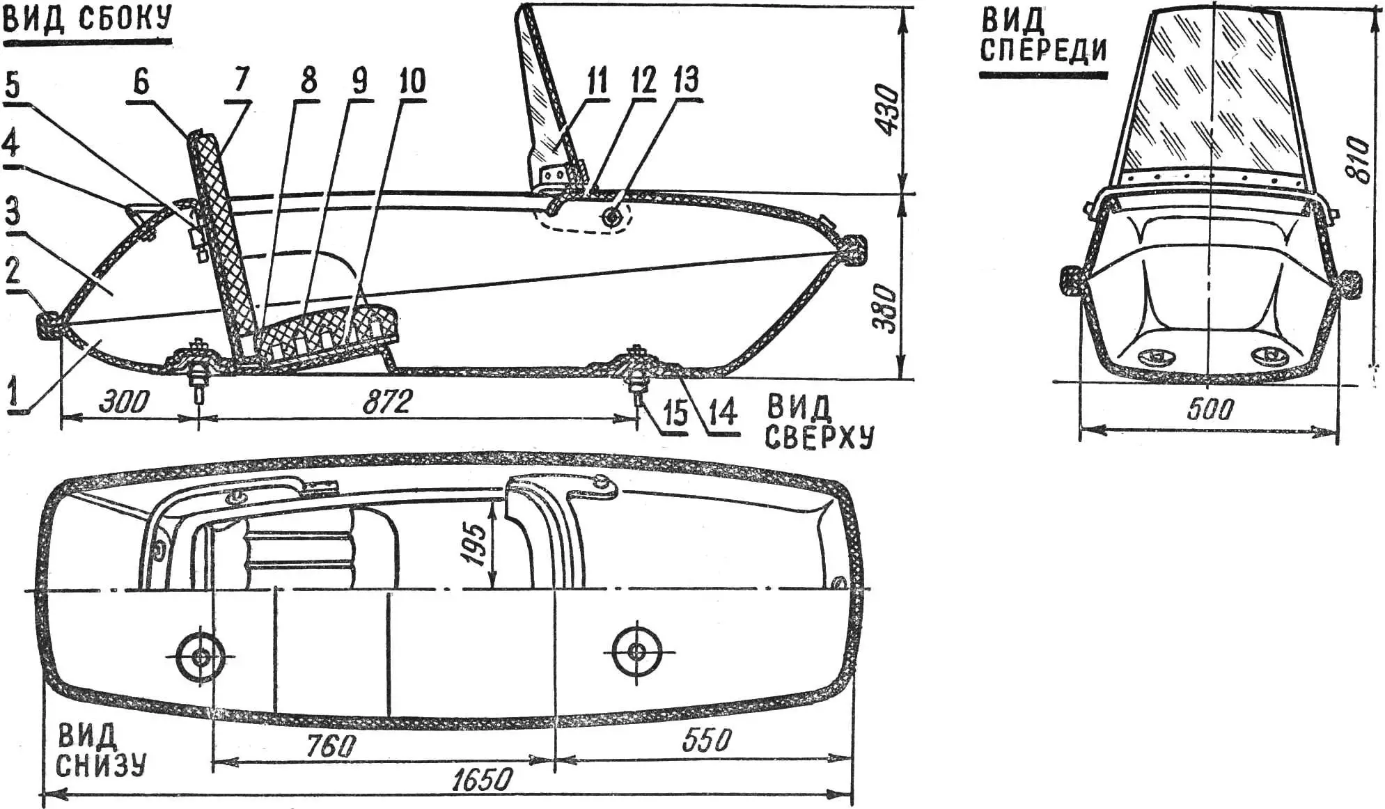
1 — lower half; 2 — edge trim (rubber); 3 — upper half; 4 — roof rail; 5 — lock; 6 — backrest base (fiberglass); 7 — cushion (foam); 8 — hinge; 9 — seat cushion; 10 — seat base; 11 — windscreen glass; 12 — screen base (duralumin); 13 — hinge; 14 — support (plate from a toy kitchen set); 15 — shock absorber (from a Neptune outboard motor).
Depending on the purpose of the body halves (fig. 1), removable inserts are placed in the mold when forming, and the joints between the inserts and the mold are sealed with clay. When laying up the lower half in the mold (fig. 2), a removable insert is installed to form the seat base. When laying up the upper half — a removable insert forming the passenger entry opening. Four aluminum plates from a toy kitchen set serve as support points for mounting the body on the sidecar frame. The plates are bonded to the lower half during molding and are therefore installed after the release layer is applied. Floor mastic is used as the release layer.

1 — panel (hardboard, plywood); 2 — block; 3 — removable insert for the body entry opening; 4 — removable insert for the seat bump; 5 — support plates (aluminum); 6 — modeling clay; 7 — strip.
The lay-up process is straightforward and has been described many times in various magazines.
Areas that need local reinforcement (seat base, future fastener locations, etc.) are built up with extra pieces and strips of glass mat.
After the resin cures, the halves are removed from the mold and finished further: the passenger opening is cut out, excess fiberglass is trimmed around the perimeter.
The surfaces of the body halves come out fairly smooth, but bubbles, bulges, etc. are still possible. These defects are filled with filler based on epoxy resin. Fine wood sawdust is a good filler. Such filler is easy to sand.
The body is painted two-tone; the colors should be close to those of the motor scooter. Keep in mind that paint quality depends heavily on surface preparation, so degrease, prime, fill, and sand first.
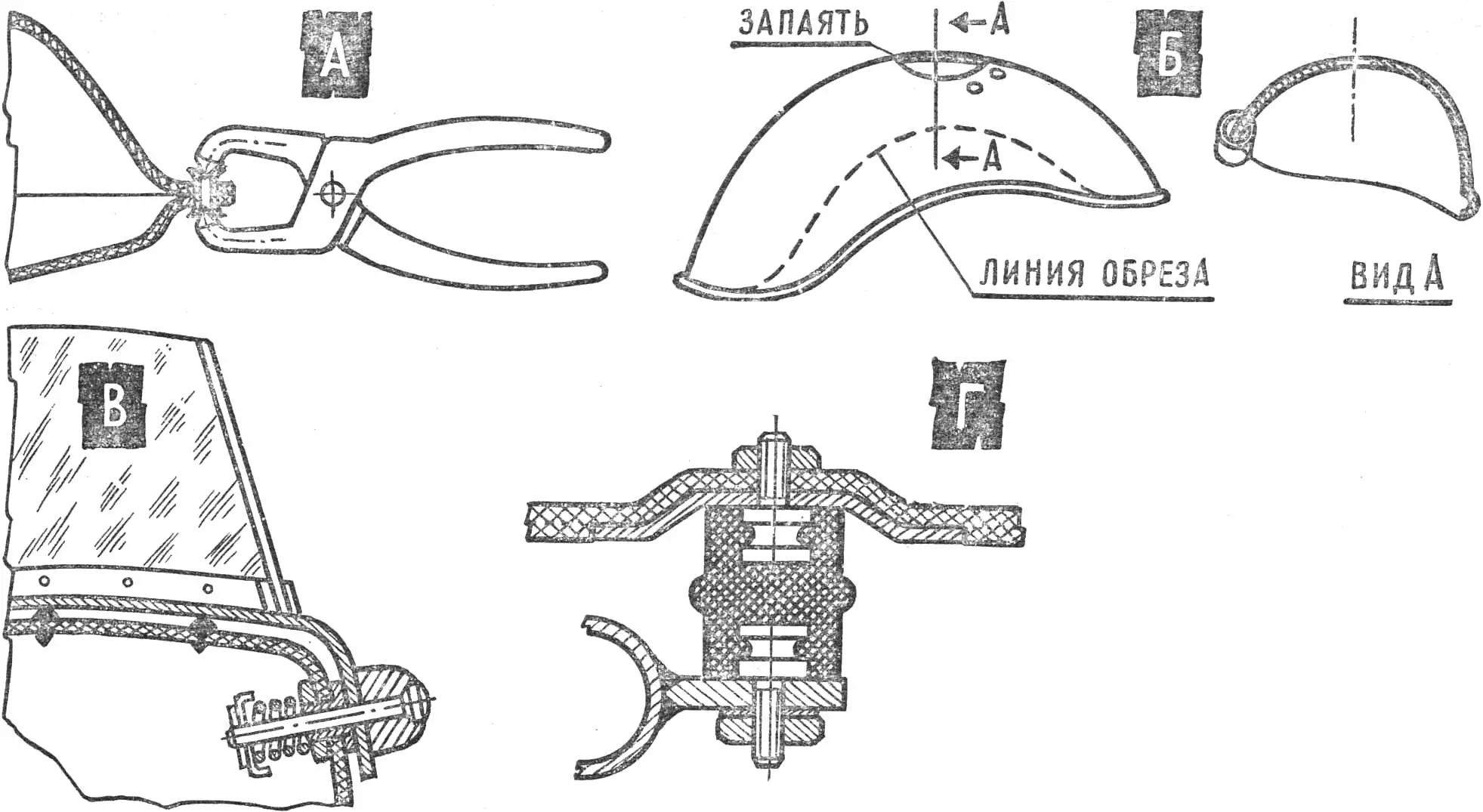
A — joining the halves; B — modifying the wheel arch; C — hinge arrangement; D — body mounting joint.
After painting, the upper and lower halves are joined with rivets made from 3 mm brass tube and a simple tool (fig. 3a) made from round-nose pliers. You can also use screws, aluminum rivets, adhesive, etc. The seam between the upper and lower halves is edged with a rubber strip cut from an Orlyonok bicycle inner tube. When stretched, the strip presses tightly against the flanges of the halves, and No. 88 adhesive keeps it from shifting.
A soft seat (fig. 1) is installed in the body: sponge rubber glued to a plywood base with many holes for ventilation and weight saving. The seat back consists of a fiberglass base with a foam cushion glued on. It is covered with leatherette matching the paint of the motor scooter and sidecar.
There is a small luggage compartment at the rear of the body, closed by the seat back, which is hinged at the lower part of the body. A lock is fitted to the back.
1 — roller bearing bush; 2 — spring damper bracket; 3 — hydraulic damper bracket; 4 — suspension tube; 5 — M10×1.5 fender mounting stud; 6 — suspension bracket; 7 — sidecar frame; 8 — grease fittings.
A mudguard from the Vyatka motor scooter is fitted on the sidecar. To give it a neat shape, a cutout is made on the outside (fig. 3b), and the cut edge is beaded or a tube split lengthwise is soldered on. The old holes are plugged. Front and rear marker lights and a stop lamp are mounted on the guard.
Automotive fog lamp diffusers were used for the lights.
The windscreen (fig. 1) is made of 4 mm organic glass, mounted on a base welded from two pieces cut from sheet aluminum.
To stiffen the screen, the glass has two sharp vertical bends. They are formed on a template after heating the glass in oil to 120—130° C.
The hinges (fig. 3c) allow the screen to fold away when the passenger gets in.
The rear of the body has decorative piping from thin-wall steel tube that acts as armrests.
The body is mounted to the frame on rubber shock absorbers (fig. 3d) from a Neptune outboard motor.
A rubber mat is laid on the body floor.
The fully equipped body weighs 24 kg.
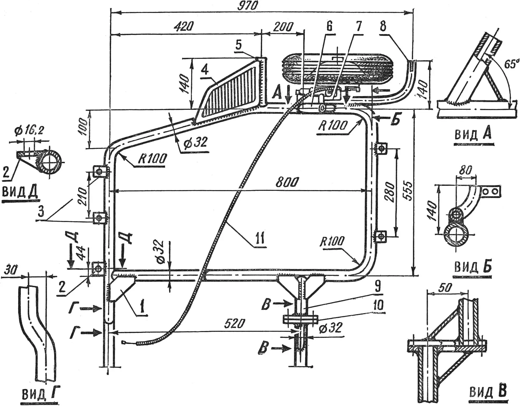
1 — gusset (1.5 mm steel); 2 — inclined tie lug; 3 — body mounting brackets; 4 — footrest; 5 — footrest bracket; 6 — suspension bracket; 7 — suspension bracket gusset; 8 — fender bracket; 9 — rear mounting bracket and gusset; 10 — flange; 11 — brake cable.
The sidecar frame (fig. 5) is welded from seamless steel tube Ø 32 × 3.0 mm, steel grade 20. On the right side, brackets for the suspension, mudguard, and footrest are welded on.
The body mounting brackets are welded to the front and rear of the frame; in addition, a bracket for the adjustable tie lug is welded to the front of the frame.
On the left side of the frame are the fittings that attach the sidecar to the motor scooter.
According to technical rules for home-built sidecars, the body frame should be 30—50 mm higher than the motor scooter frame, and the mounting points should match motorcycle attachment practice. To meet this, flanges are included in the rear mounting, the front of the frame has a suitable bend, and the mounts follow recommendations from Za Rulem, 1971, No. 7.
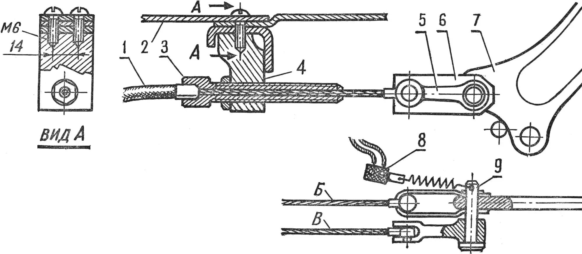
1 — brake cable outer; 2 — motor scooter footboard; 3 — adjusting nipple; 4 — nipple bracket; 5 — pull rod (Voskhod motorcycle brake lever); 6 — clevis; 7 — brake pedal; 8 — stop lamp switch; 9 — clevis pin (extended); B — rear wheel cable; C — sidecar wheel cable.
With the redesigned side stand, the front attachment method changed: the collet clamp pin is held to the motor scooter frame with a 60 mm hose clamp, welded to it.
The wheel suspension is taken from the VP-150. That allows using the axle, hub, swingarm, bushes, brackets, and brake from the same motor scooter, and the crew gains another braked wheel.
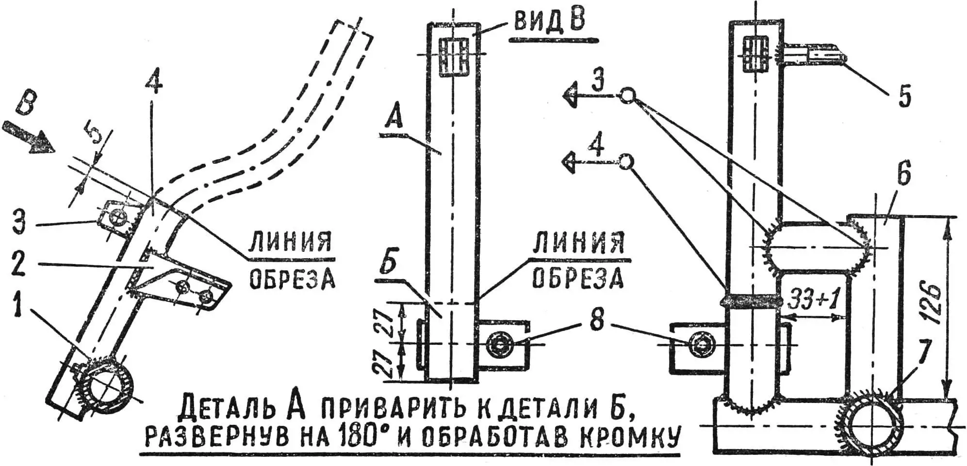
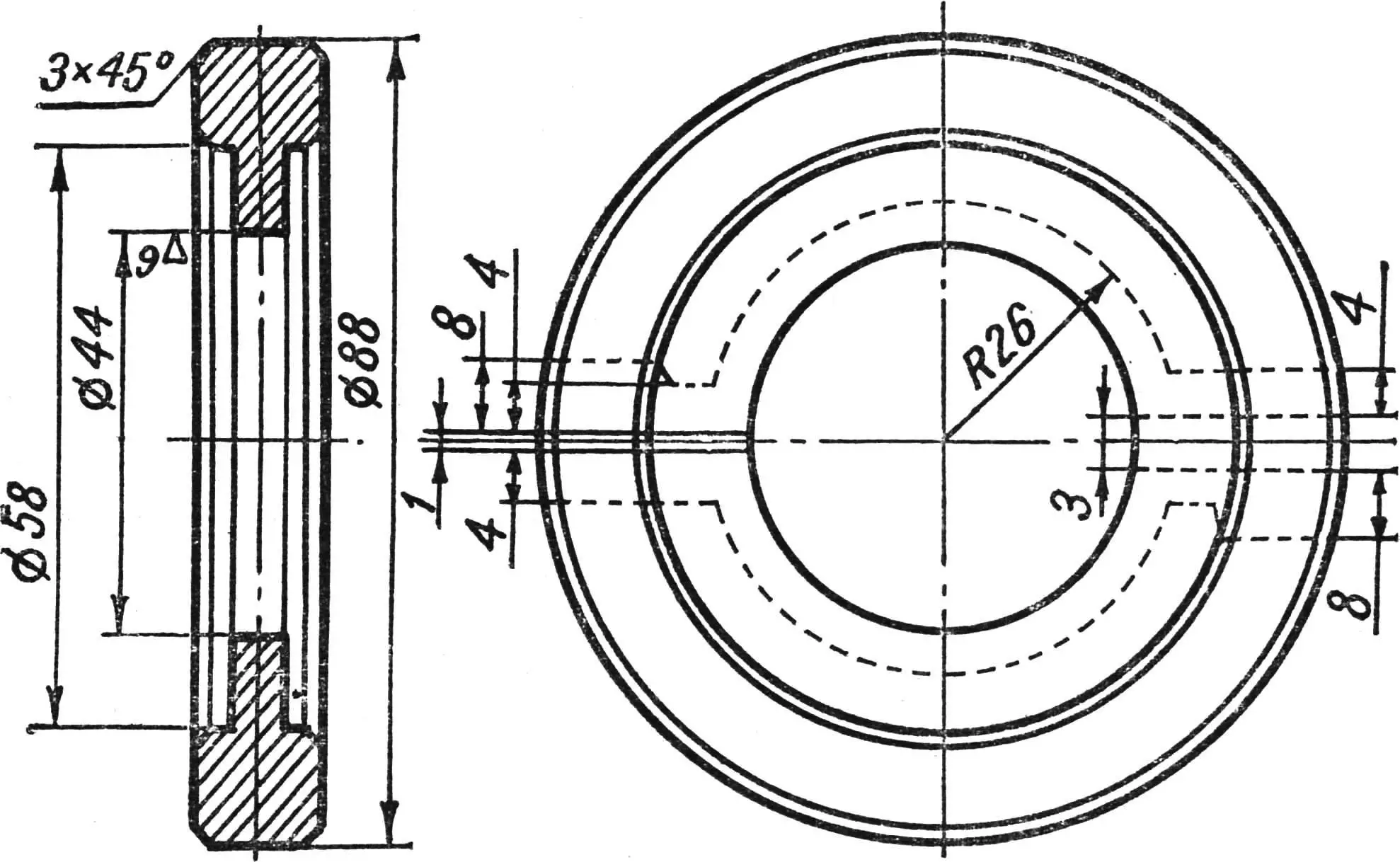
The front suspension tube (fig. 4) should be cut 5 mm above the weld joining the hydraulic damper bracket to the tube. Cut the lower part of the tube above the needle bearing bush 27 mm from its center, then rotate it 180° and weld it to the upper part.
The speedometer drive gear is removed together with its threaded sleeve, and the hole is plugged with a rubber or threaded plug.
Do not overlook this: after the modification the suspension wheel will rotate opposite to its original direction, so the left-hand-thread axle nut must be locked by lightly peening the end of the axle.
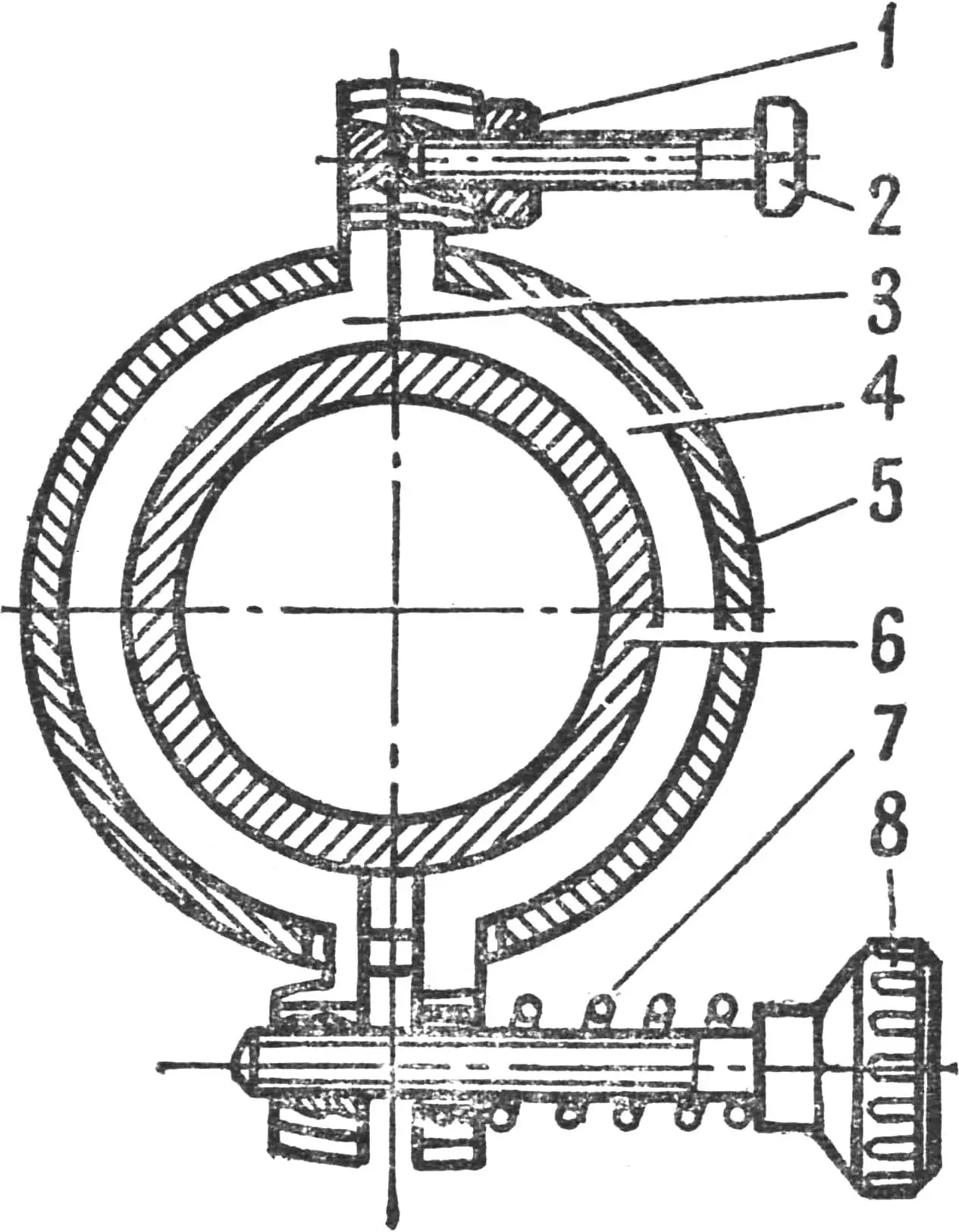
1 — M6 locknut; 2 — M6×20 bolt; 3, 4 — shoes (bronze); 5 — head tube; 6 — handlebar tube; 7 — spring; 8 — M6×40 adjusting screw.
To stiffen the suspension, a rubber rod similar to the rear bump stop of the TG-200 cargo motor scooter can be inserted inside the spring.
To join the suspension to the sidecar frame and its bracket, weld two pieces of Ø 32 × 3.0 mm tube to the tube per fig. 5, and add an M10 × 1.5 stud for the mudguard.
Equipping the sidecar with a braked wheel greatly improves safety when riding the motor scooter in town.
To connect the sidecar brake cable to the foot brake, it is easiest to use ready parts (fig. 6): the bracket and pull rod (from a Voskhod motorcycle brake lever), and the adjusting nipple from the motor scooter brake; only the clevis pin needs to be replaced with a longer one.
The stand bracket is fastened with two M6 screws, one of which also secures the floor covering. A second hole, Ø 6.2 mm, is drilled next to the first.
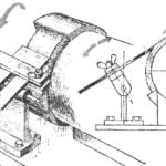
To make the motor scooter easier to handle, the handlebars are fitted with a damper. Its design (fig. 7) lets you adjust steering effort and removes wobble — a problem that puts many enthusiasts off homemade sidecars.
The main parts of the damper are bronze shoes installed instead of the felt seal in the lower part of the steering column.
Handlebar oscillation is damped by friction between the bronze shoes and the base of the steerer tube when the clamp screw is tightened.
To remove play between the shoe lugs and the slots in the head tube, the latter are spread with a screw and locknut. When installing the shoes, coat their working surfaces with CIATIM-201 grease.
«M-K» Nov. ’74, V. KOVALEV
Recommend to read
 WITH GUARANTEED ANGLE
Reground the blade plane for beginners is sheer torture. Not so just manually set the correct angle between the sand around and a piece of iron and withstand this angle throughout the... LATEST CRUISER TANKS
In the period from 1937 to 1945 in service with the British army consisted of only four types of infantry tanks. Changing models of military vehicles cruising type resembled a...
