The competition for these ship models at first glance is simple, if not primitive. What could be simpler: he included the engine, took aim and wait for the “jug” slip in a shot finish. Straightness is all that is required of the movement model class EX.
But try to design and build such microcode and you will see that this is not so easy. Although to the coveted six-foot gate, “only” fifty meters plus another dozen to the starting line, each young sportsman, for once speaking in class EX knows how to start this distance increases, turning into “as many as” sixty meters, how small see the finish from the starting gate bridge. I say suddenly rising wind totally out of place or appeared a wave, struggling to knock the boat off course, as soon will be the impression of simplicity competition. And yet there is a possibility that multiple participants will perform the race “excellent”. Then, to identify the winners, there will be additional starts, in this case, the gate width is halved and is equal to one meter!
So what should be the ideal model class EX! Try to understand. Immediately discard the planing hull configuration — hull “sniper” boats they are useless, the slightest wave that hit under the flat bottom to change the direction of motion of the model. The gliders have a low elongation, is not more of the “Troika”. We arrange a maximum elongation permitted by the rules, equal to ten. Chase high speed is not necessary, so it is possible* to live displacement contours with a maximum angle of deadrise, essentially turning the model into a large single keel. Lateral resistance of deep-seated housing is so great that to reject the vehicle from the desired course but no wind acting on the freeboard of a minimum of sail, nor the excitement of aquadrome.
However, the conditions do not completely determine the shape of the model. Their borders can be designed in a variety of devices. With one of the representatives of the “school” small models with distinct keel plane of the plate, we introduced you to the “M-K” № 2 ze 1983. And now we mikrokator a very different type.
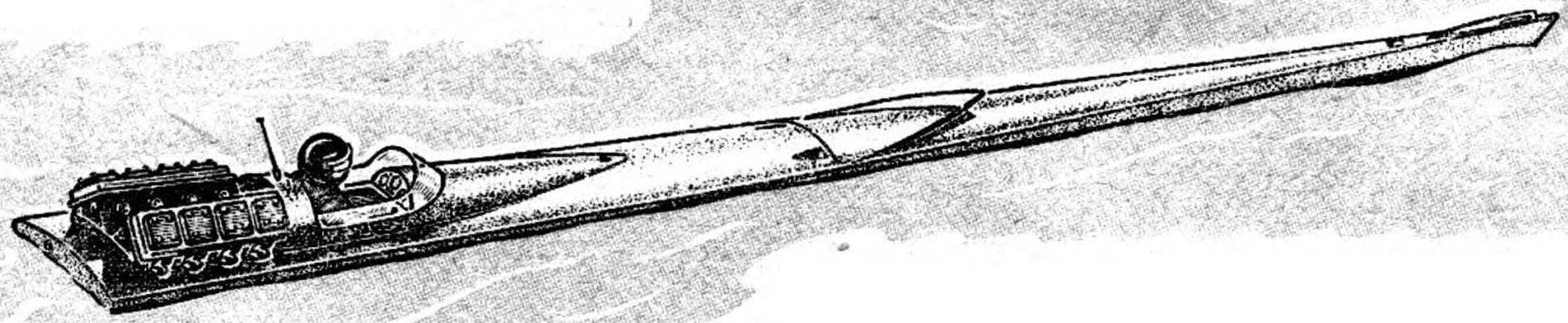
Fig. 1. Self-propelled sudomodel free design:
1 — the bow “sight” — the eye 2 — the bow of the hull, 3 — Sprayhood, 4 — slot docking of the housing halves, 5 — line connector housing, 6 — posterior part of the body, 7 — cockpit, 8 — steering figurine, 9 — feed “sight”antenna, 10 — simulate the propulsion system, 11 — rudder, 12 — ring nozzle propeller with the straightener bars 13 feed water inlet in the nozzle, 14 — keel plate, 15 — keel node joint of the housing halves.
Fig. 2. The design of the model:
1 — bow (Linden), 2 — tube, 3 — tube for filling fractions, 4 — bow plate (pine), 5 — chamber wall of the nose ballast, 6 — bow ballast (lead shot), 7 — keel plate front (pine 8X50 mm), 8, 9,13,15, 31, 32 — frames (plywood with a thickness of 3-4 mm), 10 — stringer (pine 10X10 mm), 11—front beams (pine 8X X20 mm), 12, 14 — overlays frames connector (pine 5H30 mm), 16 —pitch plate rear (pine 8X50 mm) 17 — ballast (lead shot), 18 — rear wall of the ballast chamber, 19 — tube for filling fractions, 20 — motor MU-100, 21 — cardan-coupling, 22 — propeller shaft, 23 — stern tube pipe, 24 — propeller, Ø 70 mm, 25 — transom (plywood 6 mm thick), 26 — pad stringer 27 back — stringer (pine 10X10 mm)The 28 — racer wide batteries 6МТС-9 (24 V, 9 Ah), a 29 — hatch framing (pine 8X8 mm), 30 —a box battery pack (plywood thickness of 3 mm), 33 — BIMS rear (pine 8X15 mm), 34, 35 — boss edging connector, 37 — sheathing (plywood with a thickness of 2 mm), 38 — screw to adjust the rudder, a 39 — manhole cover (on the top view shows the place of its installation).
First of all, pay attention to one important requirement of the rules. According to him the model class EX free design needs to have a appearance that allows you to accurately determine, polyopia what type of vessel she is. The detailing of superstructure and equipment, typical for this type of container, required. So, selecting as a “prototype” racing sports boat, it is easy to design a very interesting device. In the room “M-K” we talked about the impact of the sail-add-ka straightness of the turn — in procopii boats they are almost there. The choice of this type of ship is interesting and the ability to move the maximum width of the waterline at the stern. In displacement mode it is at first glance useless, because this shift is usually used to improve planing. Here, the wedge-shaped body, ends abruptly at the stern, has an increased resistance aft, which further stabilize the course of the model.
about the size. It is known that the ratio of the radius of turning of the vessel to its length is constant. Based on the foregoing, we believe that the longer the body is, the less can be a possible deviation from the target (by the way, “aim” long model is much more accurate}. The regulation permits in the class EX of the housing not exceeding 2.5 m in length — a size we will take for the new “sniper” boat.
So, basically, the model parameters were determined. A significant deadrise, wedge-shaped cross-section at the waterline with the midsection, shifted to the stern, low freeboard, the lengthening of waterline to about ten in length up to 2.5 m. it Remains to decide what form will have the frames. As requirements of speed there, take the simple triangular. To make such a case easier to any other, it is possible to control the symmetry of the contours with the highest precision using a normal line at each stage of Assembly. And the accuracy of contours depends primarily on the straightness of the turn.
R and S. 3. Connector design body:
1 — the bow of the hull, 2 — brass fungi with internal thread M6 3 — M6 brass bolts, 4 — rear part of the body, 5 — coupling.
And below deck of the connector, B — pitch of the connector.
Fig. 4. The aft part of the model and the annular channel with flow straightener grid.
Look at the drawings. You usidish any bent slats of the stringer or keel, not a single curved line shape of the frames, the camber has the only deck.
A few words about the casing. If the transportation of such a large model is not put in front of you major problems, it would be better to do without it. But if you still needed the need for the connector will appear to apply the” next technology for high-precision joining of the finished parts. Case you need to collect on the stocks as if all-in-one, with a cross-cutting longitudinal strips of the set. Between the frames bounding the bow and aft, clamped with clamps adjusted according to the thickness of the plywood plate with thickness of 4-6 mm, and the whole “sandwich” is glued in the assembled set. Further work until the skin goes with the usual case, it is cut after completion of all Assembly operations. Will only have to prepare the trim and the slats set to the longitudinal plane of the frames.
to pay more attention to the decoration of the cockpit layout steering, instruments and the power plant. Any tiny detailing “engine”, until the bolt heads and the conductors going to the “spark plugs” that will benefit the appearance of the whole model. The layout engine is the most striking decoration is pretty simple boat — that’s him in the first place to pay attention to the modelers and judges, and fans.
Ready model is loaded with ballast to obtain the precipitation is indicated in the drawing. Battery pack is specifically shifted in the stern — the maximum displacement volume of the housing here. And the placement of ballast at the ends of the housing increases the moment of inertia of the boat, thereby reducing the influence of random perturbations on the course of the model.
Fig. 5. System design adjustment of a wheel:
1 — pinion, 2 — screw M3, 3 — axis steering, 4 — rudder, 5 — bottom bearing 6 — upper bearing with oil seal, 7 — boss mounting studs, 8 — pin-retainer.
Fig. 6. The design of the stern tube seal:
1 — clamping nut, 2 housing-bearing (brass), 3 — o-ring (felt or felt), 4 — shaft tube 5 propeller shaft.
For the benefit of the straightness of motion will the installation of the annular channel of the propeller with the lattice, the straightener vanes swirling the flow of water. This device, once adjusted (bent the vertical plate of the lattice) ensure the full independence of the rate of revolutions of the propeller, even when a single-shaft scheme engine. If the fabrication of the channel for you is complicated, use the model without it. Straightener effect okolonogtevoy areas of the body a lot, and satisfactory results can be achieved by adjusting the position of the steering wheel.
Those who are not, will create such a large machine, we offer the following. One variant of the model is much less tonnage shown on the drawings. Solid lateral surface of the body preserved due to the release of the keel plate, the maximum allowable width (40 mm). The other is an exact copy of the main, made on a scale of 1:2 for all sizes, up to thickness of individual parts and sections of rails, In such a model fits produced by the domestic industry ship motoconnect. Food — 3-4 round batteries “Mars”, laid on the bottom along the keel.
M. ASHKIN, engineer
Recommend to read OILER-IMPROMPTU If the empty tube of toothpaste to fill the rear end with petroleum jelly or machine oil, and the tube to make a hole and feed it through the rod from a ball pen, as shown in the... ONE-WHEELED TRACTOR Compactness, maneuverability and good traction — the undoubted advantages of the one-wheeled tractor created at the station of young technicians in the city of Novotroitsk. They managed... Scroll back to top
 The competition for these ship models at first glance is simple, if not primitive. What could be simpler: he included the engine, took aim and wait for the “jug” slip in a shot finish. Straightness is all that is required of the movement model class EX.