 Many model aircraft model equipped with a well-established micro “Rhythm”. However, those who uses it on models-copies or RC, you know that this engine is impossible when you run the game change the speed. This can be achieved only with the improvement of the carb by creating additional devices to measure the flow of the fuel-air mixture.
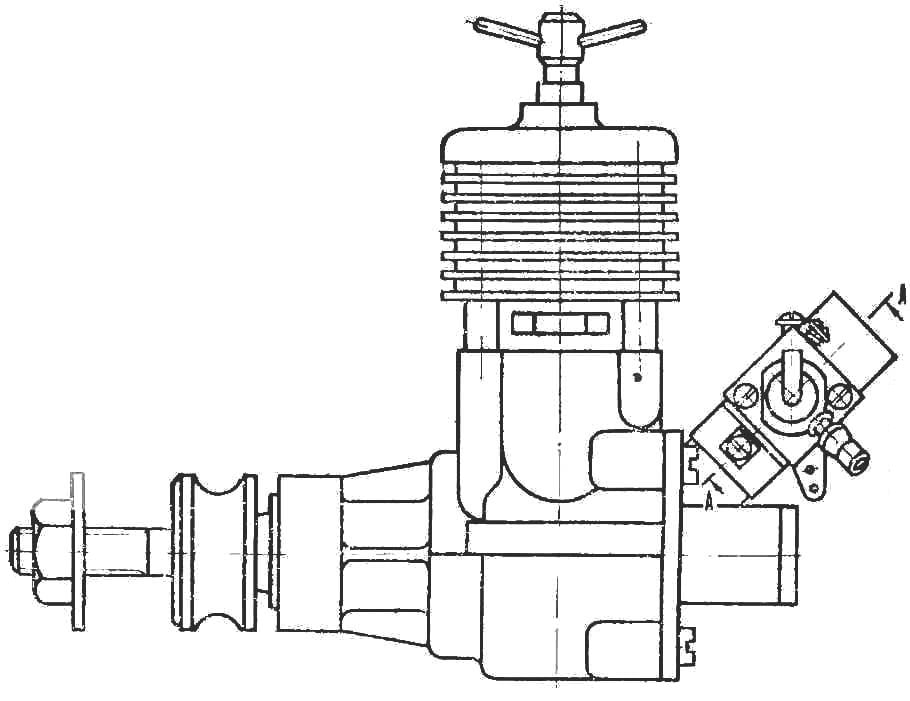
The proposed design of the carburetor, we have developed in a club of young technicians of the heavy machine tool plant in Kolomna. It is presented in the figures.
Our carburetor consists of a duralumin body (3), the nozzle (6), needle idling (1), housing air shutter (2), main metering needle (5), adjusting nut (4), lock nut small gas (12), the locking screw (9) adjustment screw air supply (10) and thrust (11).
With the engine the carburetor is connected to the transition sleeve (7) which is pressed into a pre-machined cone and fastened with two screws (8).


1 — needle idling (St-45); 2 — the case of choke (St-45); 3 — the casing of the carburetor (D16T); 4 — adjusting nut (brass); 5 — the main metering needle; 6 — nozzle (brass); 7 — reducer sleeve (D16T); 8 — bolt; 9 — screw; 10 — the screw of adjustment of air supply; 11 — thrust (St-3); 12 — locknut idling (brass).
The job of the carburetor is as follows: the fuel through a nozzle and enters the mixing chamber where it mixes with air, forming the working mixture, which then enters the combustion chamber of the engine.
For the dosage of fuel at low speed is a needle idling, which also changes the cross section of the diffuser and the hole of the nozzle, thereby decreasing or increasing respectively the flow of fuel and air.
And this, in turn, leads to a change in engine rpm. In-flight adjustment is made using thrust (11). The screw (10) is used to adjust the amount of air supplied to the carburetor.
Repeated checks of the described carb on the current model-copies of Soviet plane “YAK-18A” has shown its high reliability n practicality.
V. KLIMCHENKO, Moscow oblast


