 Generators of low frequency oscillations, as is known, can be used as a caretaker: intermittent loud noises warn of the approach of a stranger. On the same principle and made our “Keeper”. It is assembled on the transistor T1 and the transformer TR1 (Fig. 1). Load — the loudspeaker TP1. The chain of positive feedback R1, R2, R3, R4, C1 provides periodic self-excitation of the generator.
If socket G1, G2 are connected together, transistor T1 is locked, the alarm device is silent, consuming from the battery B1; a very small current (0.1 mA). In this state, he can stay as long as you want. In case of the circuit G1, G2 in the transistor T1 is opened and generated. The rhythm of the signals can be adjusted adjusted with the resistor R1, and the pitch — adjusted with the resistor R4. Consumed in this mode, the current does not exceed 5 mA.
The first and most common method of signaling is that in socket G1, G2 include the plugs SH1, R2, connected by a thin wire (Fig. 2A). It is placed around the protected object. Such a device can be used in a variety of games and attractions during a tourist trip or excursion where alarm “guard” a tent or a motorcycle.
Plugs you can connect the button with razlichayushchiesya contacts (Fig. 2B) and place it on the floor in front of the door, covered with sheet linoleum, Stepped on it, the guest includes an alarm device. And not just a guest. So can indicate the kind of kid who doesn’t reach the button on a conventional electric bell.

Fig. 1. Diagram of the alarm device.

Fig. 2. Plugs plugs
In a third embodiment, the plug engages the contact K1 (Fig. 2B). It needs to be mounted to be opened when the door is open.
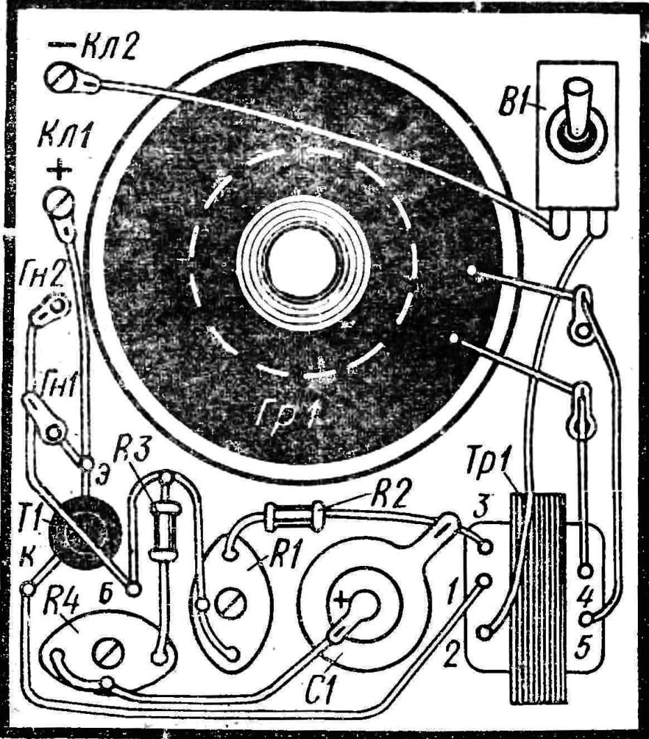
The details of the alarm Transistor T1 — type MP 39 — М1142, МП25, МГ126, P13—R16 with a gain of ?=15-25. Transformer TR1 is output from the radio “Spidola”. You can apply a homemade transformer with a core cross section of 0.5—1 cm2. Windings 1-2 and 2-3 contain 300 turns of wire sew or PEL 0,15—0,2 4-5-80 turns of the same wire O 0,25—0,35 mm. Loudspeaker Гр1 — type 0,25 GD-1 or other power 0.1—0.5 W. Battery B1—3336L (KBS-L-0,5). Other parts may be of any type.
The alarm device is mounted on the Board size 110X95 mm, made from any insulating material. For the magnetic system of a loudspeaker it is necessary to make a hole O 35 mm. the Battery is located separately from the circuit Board and connected to the clamps KL1, Кл2 flexible insulated wires.

Fig. 3. Option wiring diagrams alarm.
The establishment of the scheme is the installation of the desired rhythm and top signals adjusted by the resistors R1 and R4.
As you can see, the design of the indicator is very simple. It can be done and new ham. The scheme is absolutely safe to use, economical and does not create interference. Its application is not limited to what are listed here. Think, for example, how to use the indicator in toys or models?
V. ROMAN


