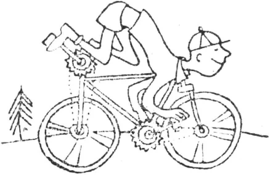
Instead of the usual steering wheel, I installed a column of the front manual drive of a two-stage chain transmission on the bicycle machine (Fig. 1). When moving, depending on the height of the cyclist, the angle of the column can be easily changed. The saddle is moved back. Both wheels are leading, have five-speed hubs. A person works with his arms and legs alternately or simultaneously. Moreover, when working with only his arms, similar to rowing, the legs can be placed on special stops.
The design of the bicycle has been changed mainly to achieve a comprehensive physical load for the person riding it. The load is not only on the legs, but is evenly distributed throughout the entire body, which makes it possible to cover long distances on highways, rough terrain, and steep climbs without much fatigue.
1 — backrest adjustment lever, 2 — backrest adjustment lever cable, 3 — spring, 4 — saddle, 5 — saddle bracket, 6 — saddle mounting clamp, 7 — adjustable backrest.
What are the technical specifications of this machine?
ADDITIONAL MANUAL DRIVE
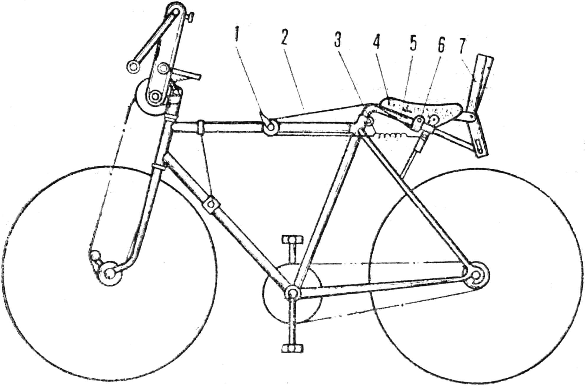
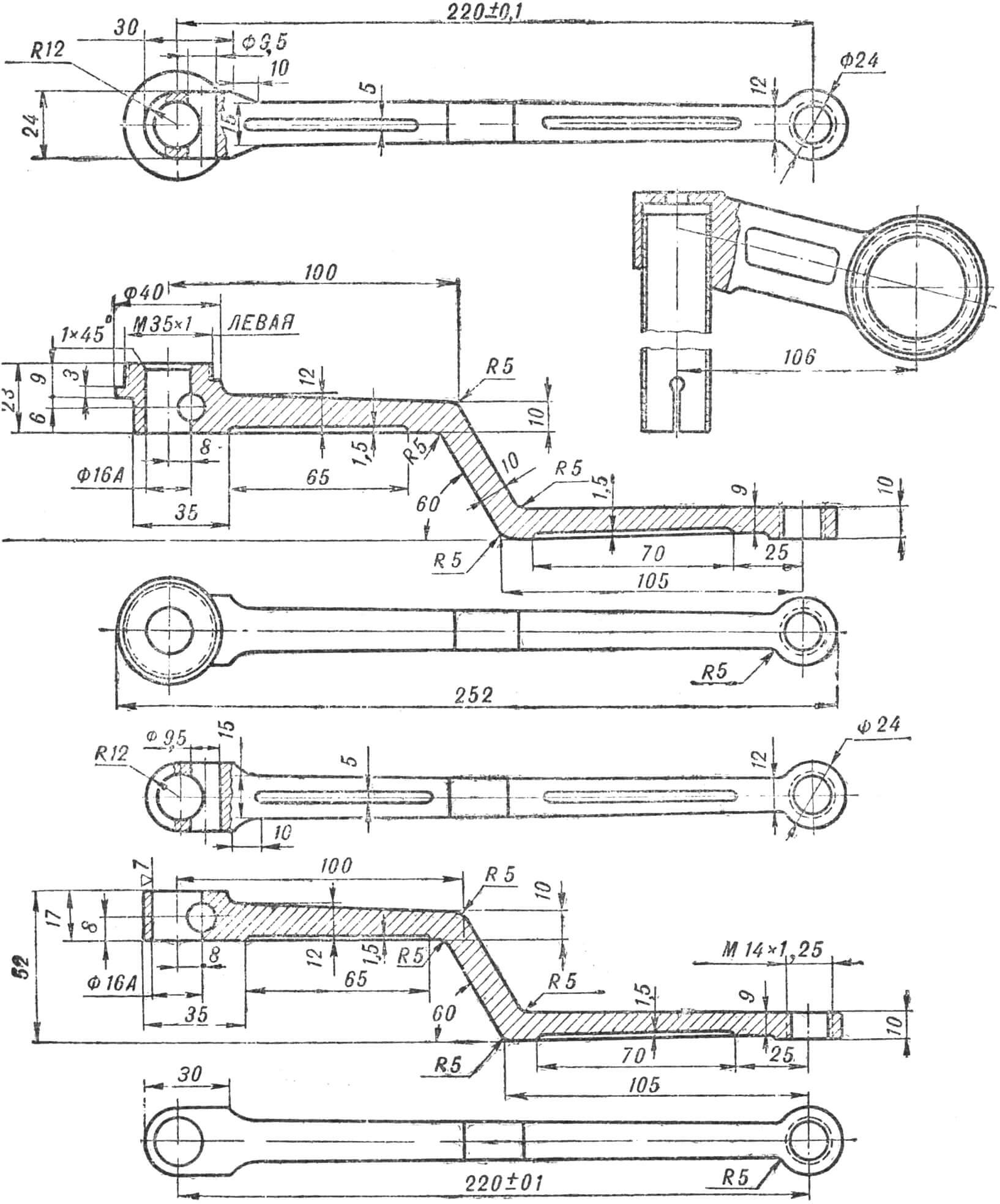
The hand drive column is pivotally attached to the front fork (Fig. 2) on the handlebar extension 18, with its upper end inclined toward the saddle. At the upper end of the column, paired handles 7 are rigidly fixed on the shaft 10, located in the same plane. The front drive handles are spaced approximately shoulder-width apart and are relatively long compared to the length of the pedal cranks, which allows the body to be engaged (in the manufactured sample, the length of the handle cranks is 220 mm). The handle shaft can be locked in any position.
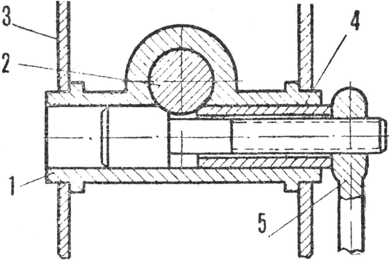
1 — tension roller, 2 — five-speed block (Z=21, 19, 17, 15, 13), 3 — chain, 4 — sprocket (Z=51), 5 — sprocket (Z=13), 6 — intermediate shaft, 7 — connecting rod, 8 — chain, 9 — drive sprocket, 10 — shaft, 11 — stopper, 12 — bracket, 13 — manual drive, 14 — rocker clutch, 15 — spring, 16 — guide rod, 17 — bracket, 18 — handlebar extension, 19 — support cables, 20 — lock, 21 — tube stop.
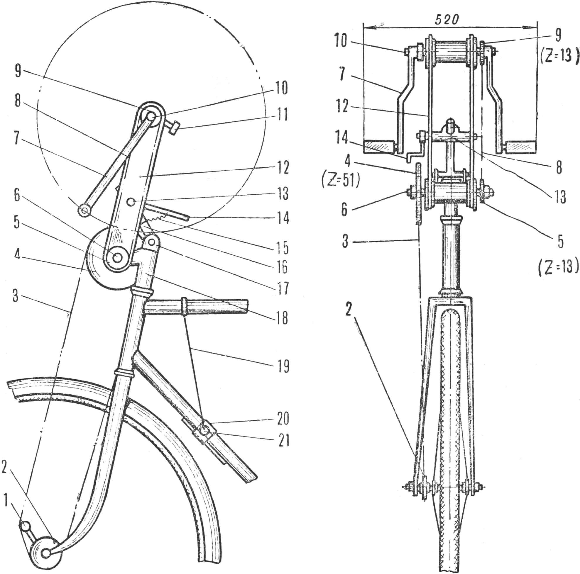
The hand drive column (Fig. 3) is assembled and consists of bushings 4 with bearings (the bushing is welded to the handlebar stem) and two bars. The column can rotate freely around the bushing axis.
1 — coupling, 2 — frame tube, 3 — bar, 4 — bushing, 5 — handle.
In a given position, the hand drive column is held by a mechanism consisting of a rocking coupling 1 connected to bars 3 and a guide rod (see Fig. 2, pos. 16) whose upper end enters the rocking coupling and whose lower end is pivotally connected to the bracket (see Fig. 2, pos. 12). The bracket is attached to the steering wheel extension with a tightening bolt. The position of the hand drive column is fixed by a coupling lock consisting of a sleeve clamp and handle 5. The lock is tightened by a spring attached to the handle and bar. A drive sprocket is rigidly fixed to the main shaft. From it, the rotational force is transmitted by a chain to the driven sprocket, which is located on the intermediate shaft. At its other end is fixed a small sprocket of a racing bicycle, from which the rotational force is transmitted by a chain to the driven sprocket, sitting on the clutch with a ratchet of the front driving wheel. The chain is held by a tension roller.
On the lower frame tube above the pedals, two-sided footrests are installed, consisting of a lock, tube stops and support cables.
The number of teeth on the sprockets is selected so that when the foot and hand drives are operating simultaneously, the gear ratio of the drives is the same.
The saddle (Fig. 4) with a backrest of an original design is attached to the seat post bracket, the end of which is directed towards the rear wheel.
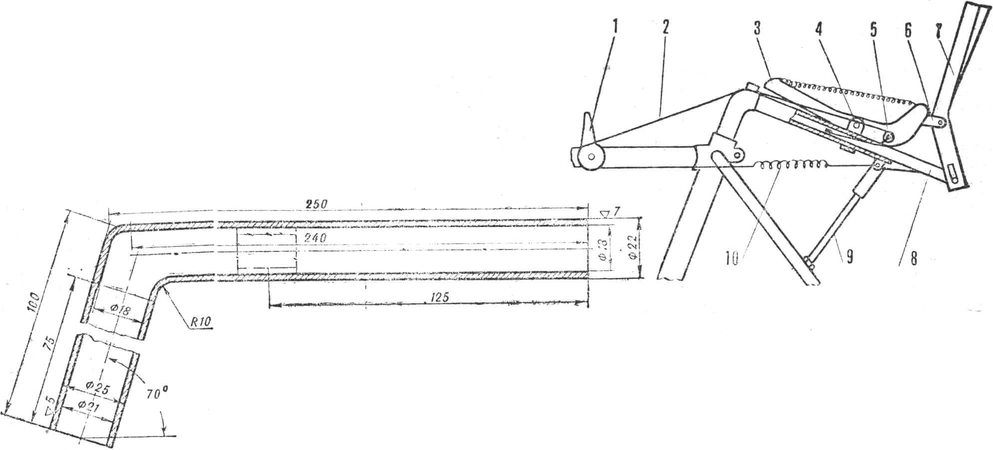
1 — backrest position regulator, 2 — cable, 3 — saddle, 4 — saddle mounting clamps, 5 — clamping screw, 6 — backrest mounting bracket, 7 — backrest, 8 — plate, 9 — stop, 10 — tension spring.
The frame (see Fig. 1) is made longer due to the fact that the hand drive column and the saddle are shifted back. Or, if the frame of a regular bicycle is used, it is lengthened by 100-120 mm with metal plates.
Braking is performed using two conventional shoe brakes on the front and rear wheels with a drive from the carriage shaft when the pedals are turned back. It is also possible to use a torpedo hub with conventional braking when the pedals are turned back.
BICYCLE OPERATION
The bike fits normally. Before mounting, the cyclist sets the optimal position of the hand drive and saddle relative to the pedals. This allows him to take a vertical body position while riding, corresponding to the minimum energy expenditure.
Depending on the road profile, the rider can rotate the front drive handles and pedals simultaneously or alternately. When working with just his hands, he can place his feet on special stops.
A bicycle is a bicycle. But even this simplest machine has enormous inventive possibilities for an inquisitive designer. In my opinion, a bicycle with an additional manual drive is within the power of any person involved in design.
L. DUTOV
Recommend to read
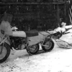 Tracked… motorcycle
The design presented here is a half-track motorcycle with a steering front wheel on a low-pressure tire and a driven track, intended for off-road travel—mainly in summer and in the... In a single pass
In one of the issues of previous years, your magazine published a note — “Again — a dowel”. It should be said that the suggested versions of a metal combined dowel are rather complex to...
