
An audible alarm on digital microcircuits for switching on/off electronic devices with 12 V power supply. There are many devices in a car that are switched on by a key or a toggle switch. The switching on of a particular device can only be controlled by the click of a mechanical switch (which may not be heard when the car is running) or visually by the position of the key (which is not easy at all when driving). With the help of the proposed electronic unit, the circuit of which is shown in the figure, it is possible to monitor the serviceability of electrical devices of a car powered by a 12 V on-board network, which are characterized by two states: on/off in a more reliable way – with the help of a sound confirmation, which is very convenient for people with impaired vision (especially “farsighted”). There are quite a lot of devices, both electrical and mechanical, for using this unit in a car: a rear window heater, a hand and foot brake, reverse gear, etc.
The unit is implemented on three popular CMOS microcircuits. When the controlled device is turned on, the alarm will briefly emit a sound signal. The same will happen when its power is turned off.
Operating principle of the device
The K561LA7 microcircuit combines four identical AND elements (with inversion) in one case. A rectangular pulse generator is assembled on inverters DD1.1, DD1.2. Its output frequency with the RC elements indicated in the diagram is about 900 Hz. From pin 4 of the DD1.2 microcircuit, rectangular pulses are constantly fed to the input of element D1.4 (pin 13), and a control signal from the K561LP2 microcircuit comes to pin 12.
At a high voltage level at the output of the DD3.1 element, rectangular pulses from the generator pass through a limiting resistor and an amplifier on the VT1 transistor to the HA1 piezoelectric capsule of the ZP-22 type (any capsule from the ZP-x model range can be used).
The audio amplifier on the transistor VT1 is necessary so that the signal of the piezoelectric capsule is clearly audible at a distance from the device itself. The transistor cascade is supplemented with the volume control R4. The transistor VT1 can be KT503, KT361 with any letter index.
When there is a low logic level at pin 12 of the control element D1.4, then at the output of this element, in accordance with the truth table of the K561LA7 microcircuit, there is a high logic level, locking the transistor VT1, therefore the emitter HA1 is not active.
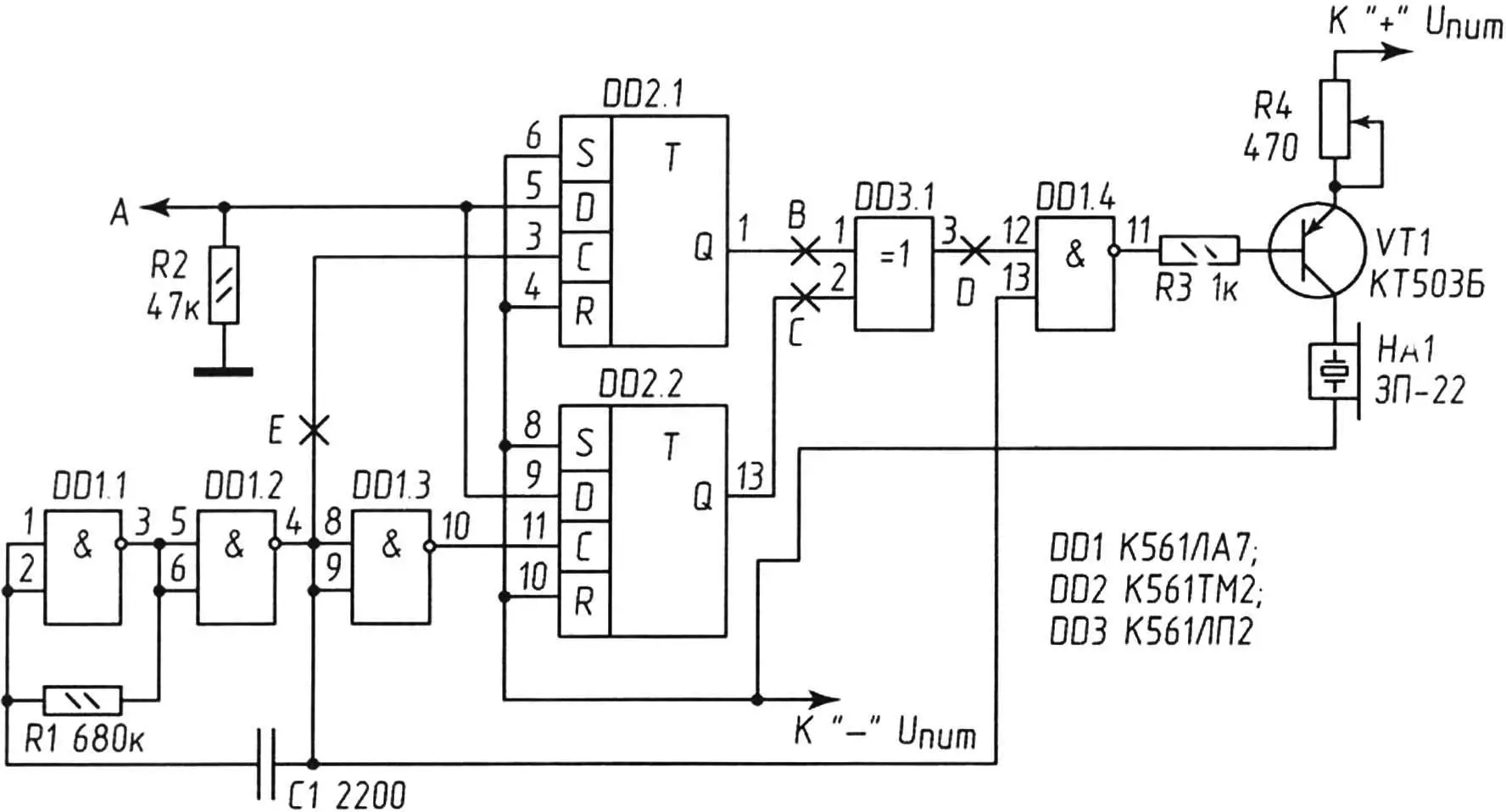
The input signal arrives at point A (see diagram) from the controlled “load”. In this case, its parameters are not important – the main thing is that it is an active load with constant resistance. The input signal is synchronous with the clock frequency of the generator, arriving at input C of the first trigger, and the signal arriving in antiphase at the input of the second trigger. The synchronization process is reduced to shifting the front of the input information pulse until it coincides with the front of the nearest clock pulse. The duration of the converted information pulses will also be determined by the duration of the synchronization frequency pulse.
The high-level input signal arriving at point A and at input D of the DD2 (K561TM2) microcircuit is a permission signal for a high-level signal to appear at the direct output Q (pin 1 of the first DD2.1 trigger) synchronously with the clock rectangular pulses coming from the generator and remain there until the high level at point A disappears. At pin 13 of the K561TM2 trigger (direct output of the DD2.2 trigger), a high level will also be established at the moment the high voltage level appears at point A. It will change to a low level with the arrival of the negative edge of the clock pulse following the disappearance of the high voltage level at point A.
At the output of element DD3.1, two pulses will be generated, tied to the front of the input signal. Short-term pulses at point D will correspond to the moment of appearance and disappearance of a high voltage level at point A, which is caused by switching on and off any consumer.
The presented electronic unit assembled from serviceable parts does not require adjustment. Immediately after assembly, it must be tested together with a stabilized 12 V DC power source. The unit connected in this way should not emit a sound signal. If you apply the power source voltage to input A of the circuit, the sound emitter HA1 should work briefly.
About the details
Fixed resistors are of the MLT-0.25 type. Variable resistor R4 is of the SP5-1 VB type.
The current consumed by the node in idle mode is 8 mA, in sound indication mode it depends on the type of emitter used, but does not exceed 25 mA.
A. KASHKAROV, St. Petersburg
Recommend to read
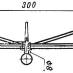 THE ROCKET PLANE “THE DUCK”
According to the rules of the competition model rocket must use only during takeoff the thrust of a jet engine, and the descent of the lifting force of the aerodynamic surface. For... THE BIKE CHANGES SHAPE
This is another publication about new ways of use of the Bicycle the inventor, V. M., Gavrilova — the inhabitant of settlement Inozemtsevo area of Zheleznovodsk in Stavropol region....
