A concrete mixer is not needed by everyone. But it will certainly interest those who are planning to build something on their homestead or are already building.
The design of the proposed concrete mixer is simple and accessible for replication. It uses fairly common components and parts. However, it can be assembled from other available materials, and the description published here should be considered as an example.
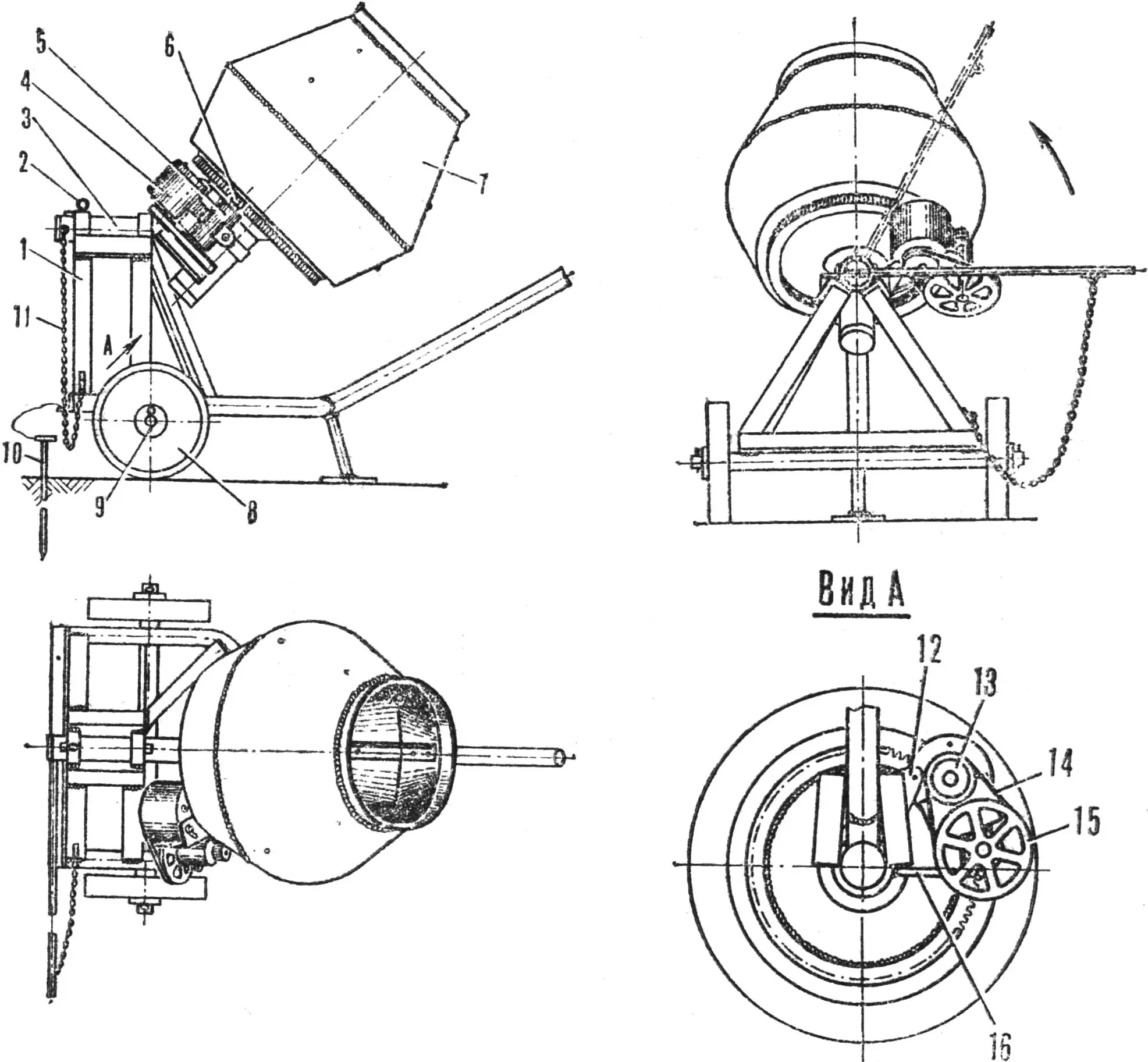
The concrete mixer (Fig. 1) consists of a frame, a rotating device, an electric motor, a gearbox, a drum with an axle, and grounding.
Fig. 1. General view of the concrete mixer:
1 — frame, 2 — pin for fixing the rotating device, 3 — rotating device, 4 — electric motor, 5 — gearbox, 6 — drive gear, 7 — drum, 8 — wheel, 9 — wheel pin, 10 — grounding, 11 — limiting chain, 12 — motor mount, 13 — drive pulley, 14 — belt, 15 — driven pulley, 16 — tension bolt.
The frame (Fig. 2) is assembled from inch pipes and angles. A wheel axle is attached to the bottom—a solid steel rod Ø 43 mm, the ends of which are turned to Ø 41.5 mm. Worn track rollers from a crawler tractor, for example, are fitted here. The wheels are held from slipping off by wire pins Ø 6 mm. At the front, under the base of the handle, there is a foot—the third support point of the concrete mixer. The triangle of the frame is crowned by an M-shaped structure—a bed for the rotating device. At its edges are two ring-bearings with an internal Ø 62 mm. The latter, as well as the frame parts, axle, and foot are fastened by welding.
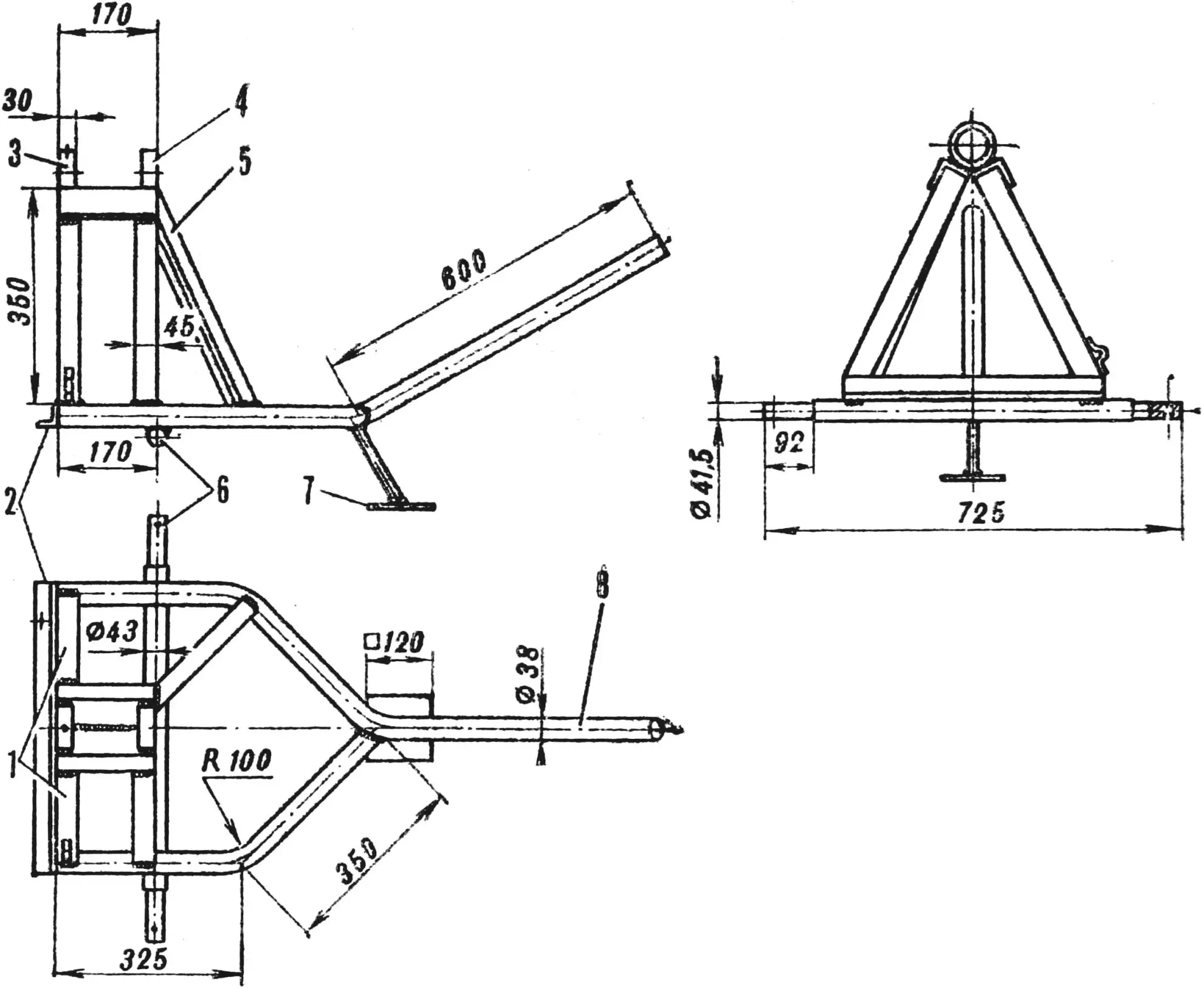
1 — front struts, 2 — front angle, 3 — front ring-bearing, 4 — rear ring-bearing, 5 — rear strut, 6 — wheel axle, 7 — foot, 8 — handle.
A loop for attaching the limiting chain (its purpose is described below) is welded to the front left angle-strut, and a hole is drilled in the front horizontal angle for connecting the wire coming from the grounding.
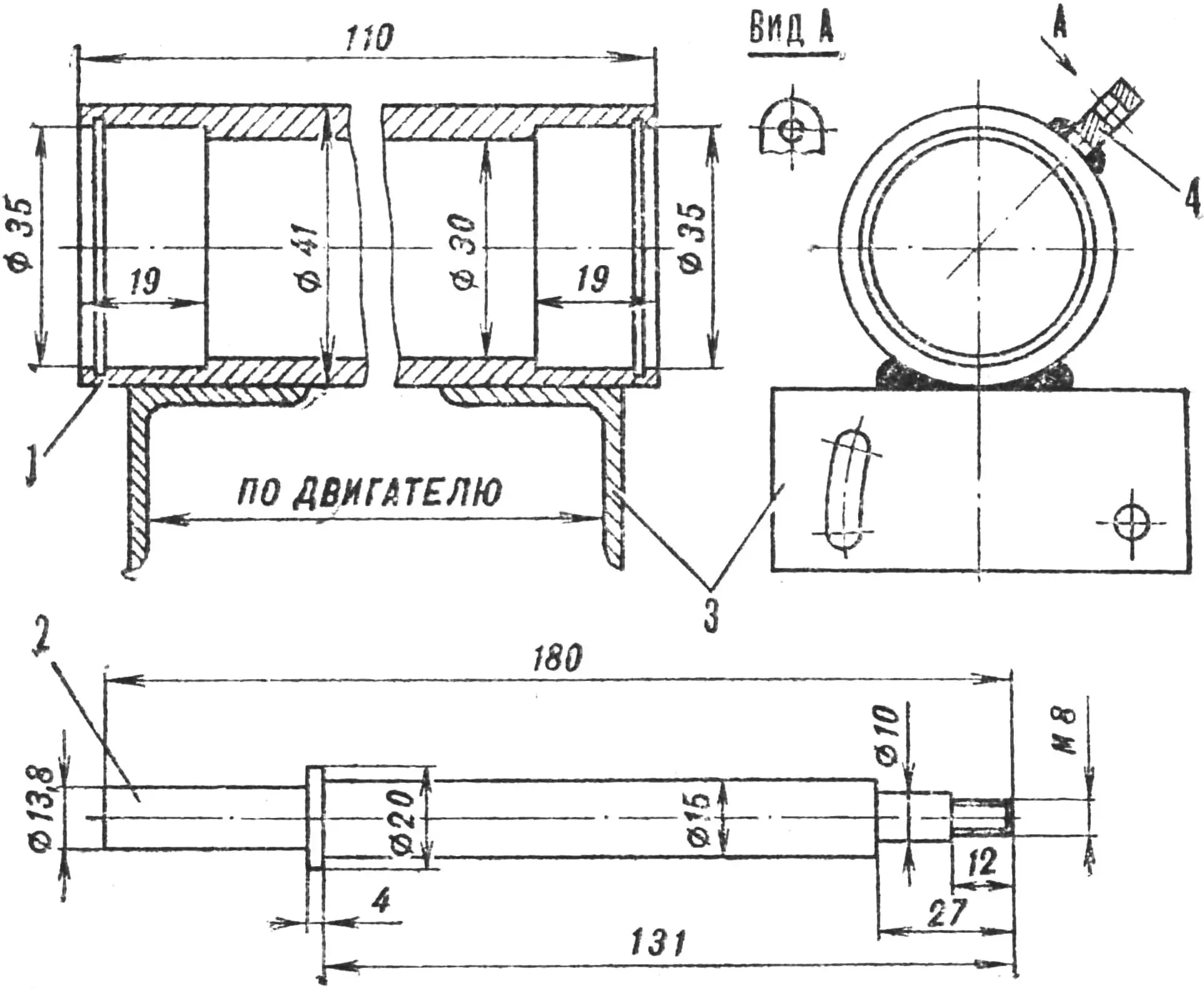
The rotating device (Fig. 3) is designed for tilting the drum and pouring concrete. It is assembled from two tubes Ø 60 mm, a bearing housing, two angles—stiffening ribs, two stops, a tilting handle, and a plug. All named parts are connected by welding. The rear stop, handle, and plug are welded after the rotating device is installed in the ring-bearings of the frame. Then it can rotate in the rings without sliding out of them. The rotating device is fixed in the working position by a wire pin Ø 8 mm. For it, a vertical diametrical hole is drilled in the front ring (together with the tube of the rotating device).
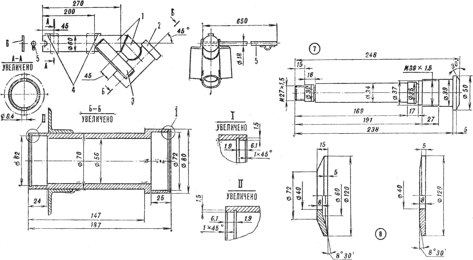
1 — tubular base, 2 — bearing housing, 3 — stiffening rib, 4 — stops, 5 — handle, 6 — plug, 7 — drum shaft, 8 — profiled washers.
A loop connected to the other end of the limiting chain is also welded to the end of the tilting handle.
The bearing housing is turned from a thick-walled steel pipe. It houses ball bearings No. 206 and No. 207, held by spring thrust rings, and the drum shaft, turned from a forging. A hole is made in the bottom of the drum where this shaft is inserted and secured with two profiled washers and a nut. In the bearings, it is also held by a nut screwed onto the shank.
The drum (Fig. 4) is welded from five elements: a base (a suitable concave disc can be used), two conical surfaces from 1.5 mm steel sheet, a reinforcing ring-rim at the entrance, and a toothed ring (from the flywheel of a GAZ-51 car engine). Three blades that mix the concrete are riveted inside the drum. They are made from angles bent according to the internal contours of the drum.
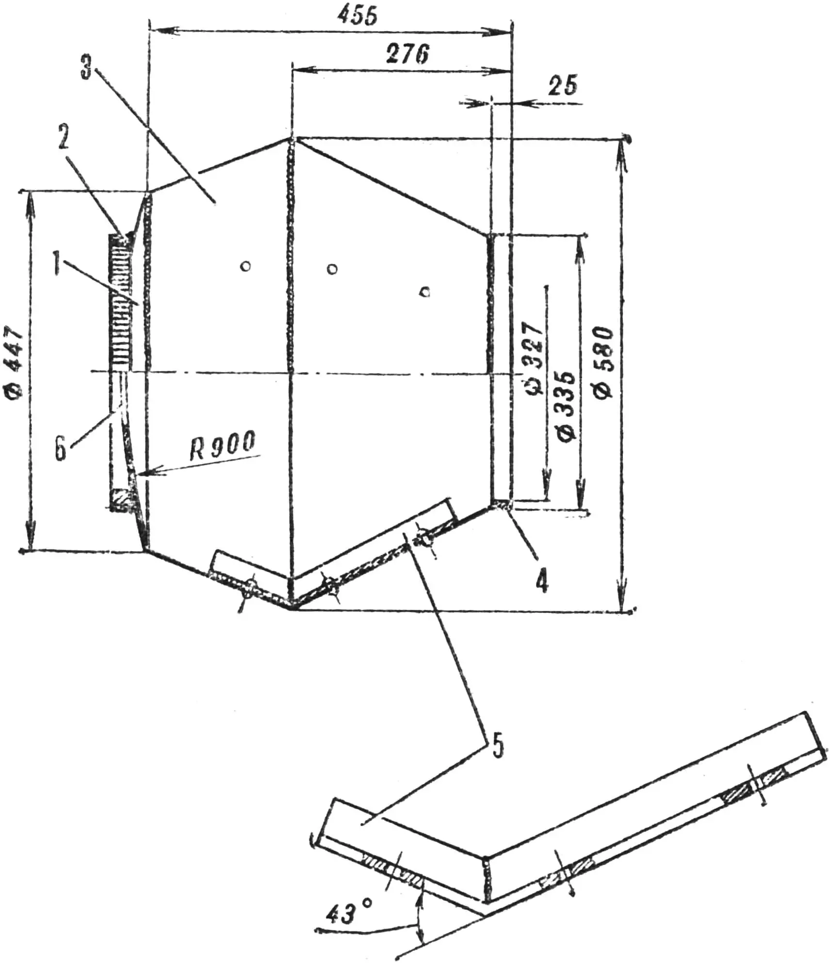
1 — convex bottom, 2 — toothed ring, 3 — drum body, 4 — ring-rim, 5 — blade, 6 — hole for shaft.
A few words about the motor and gearbox. The concrete mixer design uses an electric motor, pulleys, a V-belt, and a push-button switch without a protective thermal relay from a worn-out washing machine (see Fig. 1). The motor is attached to the rotating device in place with steel strips (one end of the strip is screwed to the motor, and the other is welded to the tubes of the rotating device).
On the other side of the electric motor, the housing of the intermediate shaft—the main part of the gearbox (Fig. 5)—is fixed at four points (two on each of its ends). The holes in the mounting angles are different: two are cylindrical, and two are arc-shaped; with their help, the tension of the V-belt on the motor and intermediate shaft pulleys is adjusted. The shaft itself rotates in two No. 202 bearings seated in the housing, and its other end is equipped with a gear from a GAZ-51 starter.
1 — housing, 2 — intermediate shaft, 3 — mounting angles, 4 — eye.
The housing has an eye into which a tension bolt is inserted: by moving the eye with nuts along the bolt, the pressure of the starter gear against the toothed ring of the drum can be increased or decreased. The other end of the bolt is welded to the bearing housing of the rotating device.
The concrete mixer ready for work is loaded through the entrance with the necessary components: sand, cement, water, and other additives, and the electric motor is turned on. During rotation, static electricity may form from the friction of the mixed mass against the drum walls, which will be discharged to the ground using portable grounding—a metal stake with a conductor connected to the frame.
When the concrete is ready, the motor is turned off and, after waiting for the drum to stop, it is tilted by the handle. Excessive tilting is prevented by the limiting chain.
«M-K» 5’83, T. MYAKSHITSKY
Recommend to read
 MAGICAL TRANSFORMATIONS OF PAPER
His appearance in the editorial was met with a, frankly, no enthusiasm; preliminary telephone conversation were no signs, it seemed, nothing sverhinteresnogo. Homemade paper? Well,... ARCHED GREENHOUSE
Greenhouses, of course, not a fad or fashion, and suffered many a necessity. After all, these buildings, covering a plot of land of glass or plastic, allow * not only early to plant the...
