
You have built a sailing craft — a yacht, dinghy, catamaran, or simply fitted a kayak with a sail. There is no doubt that the main attention was given to making the hull, mast, and sails. The small, at first glance inconspicuous fittings of a sailboat are remembered at best after construction is finished, or even after launching and the first trial sail. Yet these parts are nevertheless an organic component of the vessel.
By the tasks they perform, all sailboat fittings (Fig. 1) can be divided into devices for securing and adjusting standing rigging, for securing running rigging, for sail control, and finally for mooring and towing the vessel.
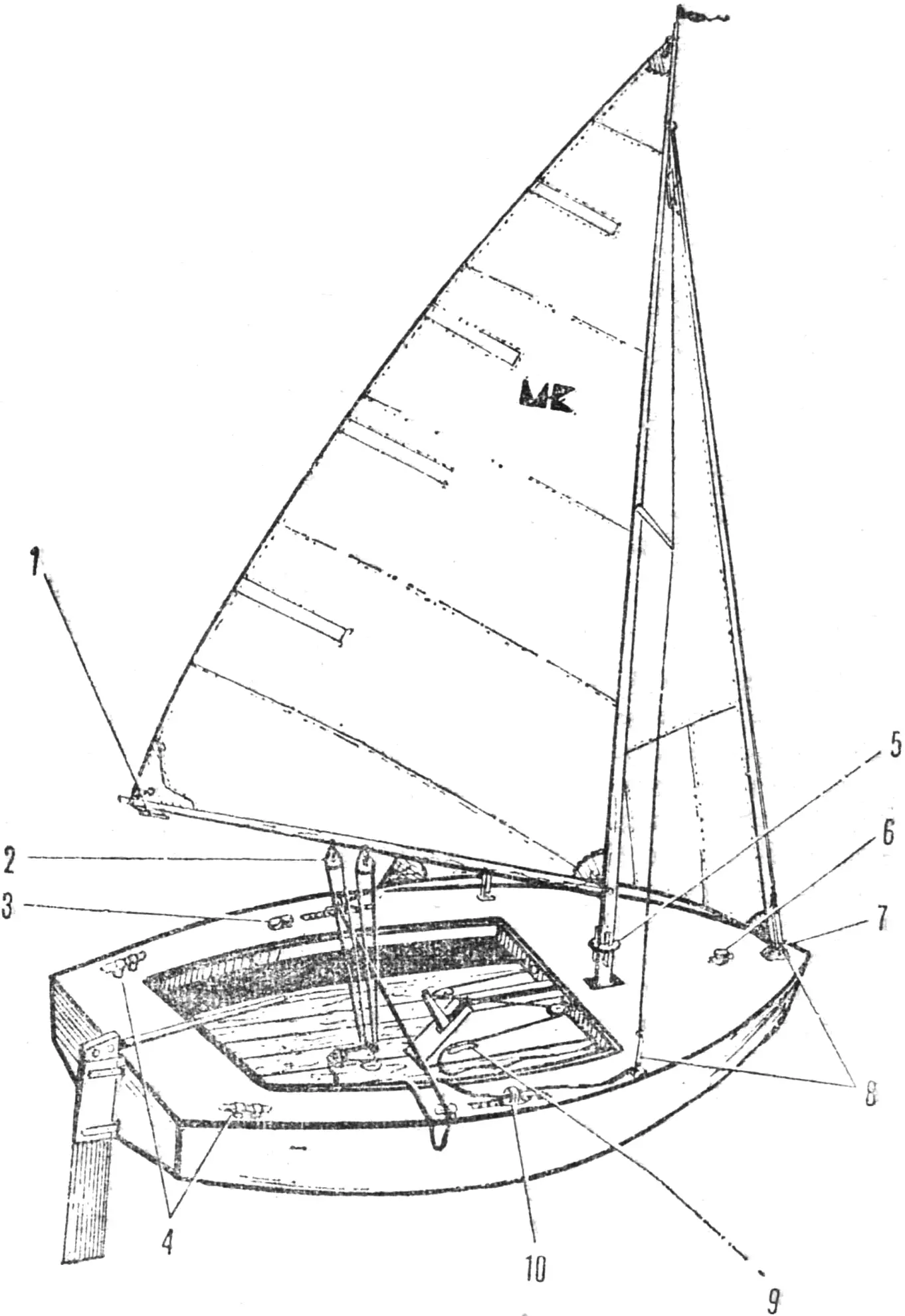
1 — cleats, 2 — blocks, 3 — stopper, 4 — bollards, 5 — belaying pin with belaying-pin ring, 6 — bitts, 7 — shackle, 8 — turnbuckles, 9 — cleats, 10 — fairlead tracks.
Standing rigging consists of steel, natural-fiber, or synthetic ropes that hold the mast upright. These include forestays, shrouds, and braces. These ropes are connected to the sailboat’s hull by metal plates or brackets (chainplates) and tensioning devices (turnbuckles).
The simplest device for tensioning stays and shrouds is the so-called soft turnbuckle (Fig. 2). It is a length of natural-fiber or synthetic rope repeatedly passed through a chainplate and a ring spliced into the stay or shroud. Despite its extreme simplicity, such a turnbuckle allows mast position and standing-rigging tension to be adjusted over a very wide range and, when needed, makes it possible to quickly disconnect a shroud or stay from the corresponding chainplate.
A variant of this device is the deadeye turnbuckle (Fig. 3). In shape a deadeye resembles a lentil with three holes drilled in it. A natural-fiber rope is passed through them, forming a kind of tackle. The advantages and disadvantages of such a turnbuckle are the same as those of the soft one. Deadeyes are seldom seen on sailing craft today.
On modern yachts, metal turnbuckles are usually used — flat and screw types. The former are easier to make yourself (Fig. 4). They are metal strips (stainless steel) with holes drilled along their entire length. The strips are placed parallel to each other and joined by bolts. The same bolts connect the turnbuckle to the chainplate and the corresponding standing-rigging rope. Tension is adjusted by moving the bolts from one hole to another.

Fig. 3. Deadeyes: 1 — deadeye (wood, textolite, Ø 80 mm), 2 — natural-fiber or synthetic rope (turnbuckle).
Fig. 4. Flat metal turnbuckle: 1 — M6 bolt with nut, 2 — plate (stainless steel), 3 — chainplate.
Fig. 5. Screw turnbuckle: 1 — pin, 2 — shaped M6 bolt, 3 — threaded barrel.
Fig. 6. Rigging shackle: 1 — rigging shackle, 2 — bolt.
Fig. 7. Simplified rigging shackle: 1 — shackle, 2 — bolt.
Fig. 8. Simplified rigging shackle with cylindrical pin: 1 — shackle (steel S 1.5 mm), 2 — pin Ø 5 mm, 3 — retaining groove, 4 — pin Ø 1 mm, 5 — shaped hole.
Fig. 9. Rigging shackle for a kayak: 1 — shackle, 2 — bolt.
Screw turnbuckles are much more convenient. They consist of three parts — a threaded barrel (body) and two screws, one with a right-hand thread and the other with a left-hand thread. The threads inside the barrel are made accordingly. By turning the barrel, you can adjust the tension of shrouds, stays, and other rigging elements over a fairly wide range.
The turnbuckle shown in Figure 5 is suitable for small tourist sailing craft (up to 4–5 m long). Any non-corroding alloy can be used for it — stainless steel, brass, or bronze — but ordinary steels may also be used with subsequent chrome plating, cadmium plating, or zinc plating.
Running rigging includes sheets and halyards — ropes for controlling sails and hoisting them on the masts. They are secured with various rigging shackles. These are made of round or sheet steel (Figs. 6–9). The shackles are “closed” with bolts of the appropriate diameters. Instead of a bolt, a cylindrical pin with a pressed-in cross pin is often used (Fig. 8), and a shaped hole (with a slot for the cross pin) is provided to lock the pin. The pin is inserted into it and turned 90°. A groove stamped on the shackle prevents it from rotating and thus locks it in place. The main shackle dimensions are given in Table 1.
Table 1
| L mm | l mm | Shackle diameter, mm |
|---|---|---|
| 32 | 11 | 5 |
| 38 | 14 | 6 |
| 54 | 17 | 8 |
| 54 | 17 | 10 |
The working ends of sheets and halyards on sailing craft are made fast on devices such as cleats, belaying pins, and stoppers of various designs. Cleats and belaying pins are used for long-term securing of lines (when the line does not have to be worked constantly); in other cases stoppers are used.
Cleats (Fig. 10) are posts of a distinctive shape. They are made of wood, metal, or plastic. Lines are secured to them with a figure-eight hitch (Fig. 11). Cleat sizes (see Fig. 12, Table 2) depend on the rope diameter and the loads applied to it.
Table 2
Dimensions in mm (see Fig. 12)
| A | B | C | D | E | F | G | H | I |
|---|---|---|---|---|---|---|---|---|
| 35 | 500 | 65 | 250 | 22 | 25 | 55 | 180 | 16 |
| 25 | 400 | 50 | 200 | 16 | 22 | 40 | 145 | 12 |
| 20 | 300 | 40 | 150 | 12 | 16 | 30 | 110 | 10 |
| 12 | 200 | 25 | 100 | 8 | 12 | 20 | 75 | 8 |
| 10 | 150 | 20 | 75 | 6 | 8 | 16 | 55 | 6 |
| 6 | 100 | 12 | 50 | 4 | 6 | 10 | 35 | 4 |
Belaying pins (Fig. 13) are metal pins inserted into a pin rail or into a belaying-pin ring (a ring fitted on the mast). Halyards are made fast on a belaying pin in the same way as on a cleat — with figure-eight turns. Unlike a cleat, a belaying pin makes it possible to free the belayed halyard instantly — simply by pulling the pin out of the rail or ring.
Jib sheets and mainsheets — that is, lines for sail control — are secured on yachts with various stoppers. There are a great many designs: cam, eccentric, roller, slot… But they all have the same task — freely allowing the rope to run in one direction while wedging (stopping) it when it moves the opposite way. Variants of eccentric stoppers are shown in Figure 14, and the design in Figure 15.
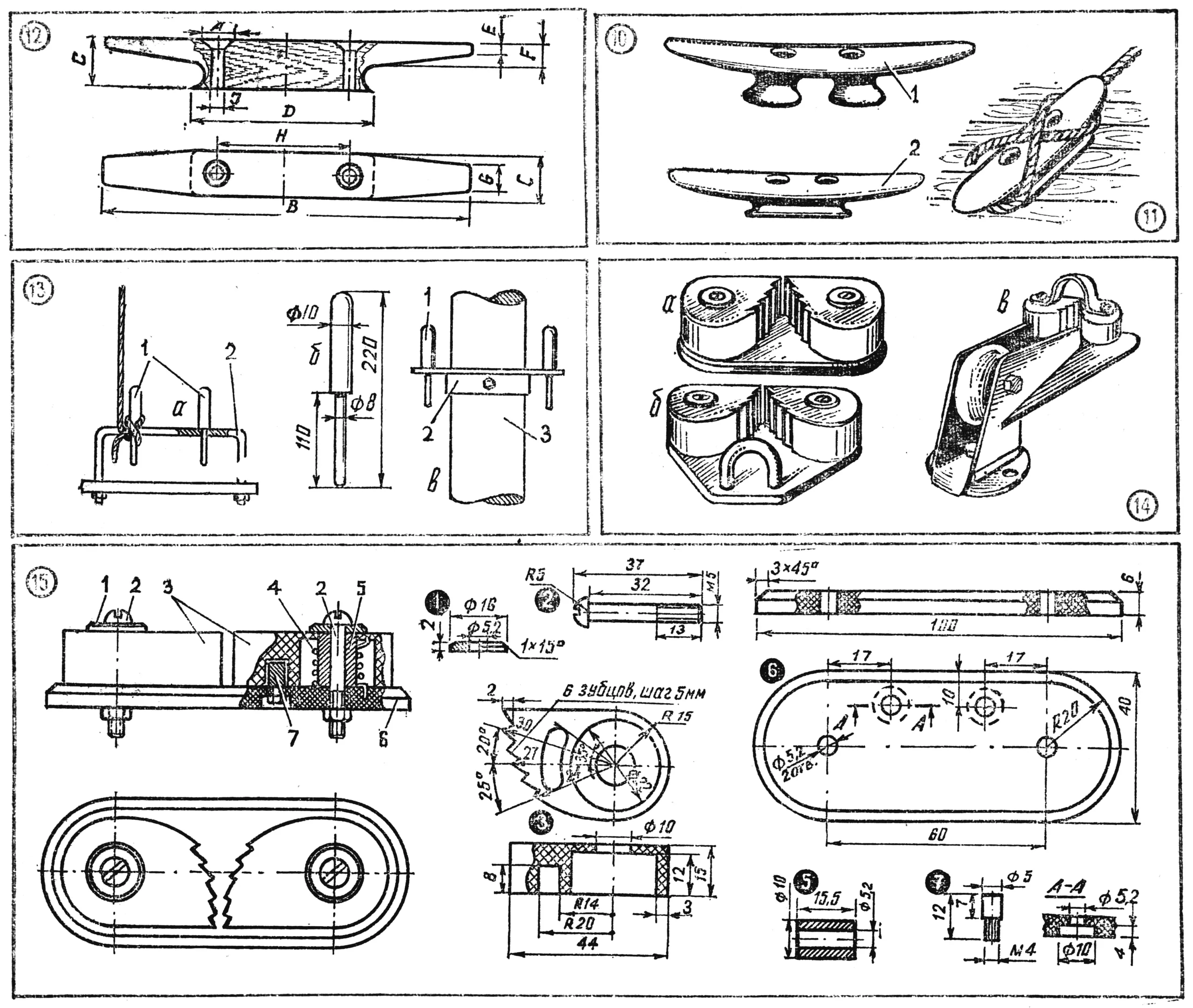
Fig. 11. Method of securing a line on a cleat.
Fig. 12. Dimensions of the most commonly used wooden cleats.
Fig. 13. Belaying pins: a) belaying pins on a pin rail, b) belaying pin, c) belaying pins on a belaying-pin ring: 1 — belaying pin, 2 — belaying-pin ring, 3 — mast.
Fig. 14. Eccentric stoppers of various designs: a) eccentric stopper, b) stopper with a shackle, c) combination of a stopper with a fairlead roller.
Fig. 15. The most common eccentric stopper design: 1 — washer (brass, duralumin), 2 — M5 bolt (steel, brass), 3 — eccentric (textolite, getinax), 4 — spring (high-carbon steel wire, Ø 1 mm), 5 — bushing (brass, duralumin), 6 — base (textolite, getinax), 7 — stop (brass, steel).
One of the most critical sailboat fittings is the block. As is well known, one movable block gives a twofold mechanical advantage. For a greater advantage, blocks are combined into tackles used to control the mainsail (Fig. 16). The mechanical advantage is judged by the number of parts of the fall — that is, the ropes forming the tackle. Thus, a two-part sheet lead gives a twofold advantage, and a four-part lead a fourfold one.
Blocks of various designs generally consist of the same parts. The heart of a block (Fig. 17) is a plastic or metal sheave — a pulley with a groove along which the rope runs. The sheave sits between metal or plastic cheeks and is joined to them by an axle (pin). If the cheeks are plastic, the pin is secured to a strap — a bent metal strip that is also used to hang the block. Structurally these devices may be single-sheave or multi-sheave, but as a rule no more than three sheaves are combined in one block.
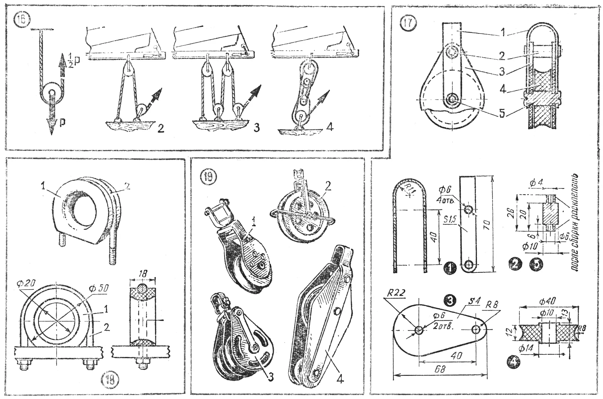
Fig. 17. Single-sheave block design: 1 — strap (steel S 1.5 mm), 2— spacer bushing (steel, brass), 3 — cheek (textolite, getinax, S 4 mm), 4 — sheave, 5 — pin (steel).
Fig. 18. Fixed fairlead: 1 — ring, 2 — bracket.
Fig. 19. Blocks of various designs: 1 — single-sheave block with metal cheeks and a swivel, 2 — lightweight single-sheave block with a swivel, 3 — double-sheave block, 4 — variant of a double-sheave block.
Block sizes are determined by sheave sizes. It should be noted that with small-diameter sheaves there are large losses due to rope bending, so the optimum sheave diameter is four to five times the diameter of the rope used. The sheave width is chosen so that the rope, running in the groove, does not touch the cheeks. This condition is met when the width equals 1.4–1.5 times the rope diameter. Single- and double-sheave blocks are shown in Figure 19, and their drawings in Figures 17 and 21.
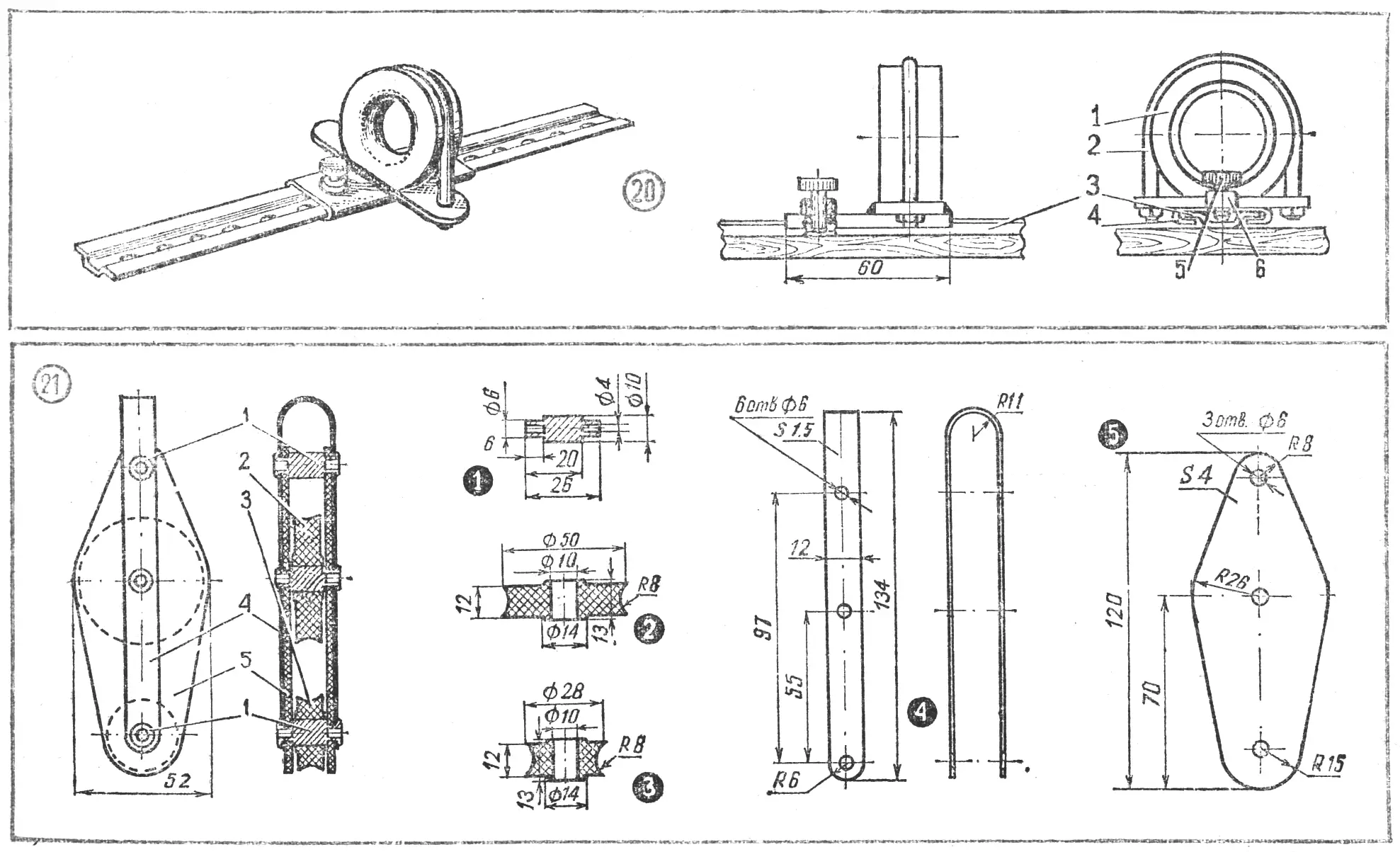
Fig. 21. Double-sheave block: 1 — pins (steel, brass), 2 — large sheave, 3 — small sheave, 4 — strap (steel S 1.5 mm), 5 — cheek (textolite, getinax).
For leading running rigging (sheets), fairleads are used — rings with openings whose sharp edges are rounded. They are fixed rigidly on the hull or on tracks — fairlead rails along which they can move. Fairleads are made of metal or plastic (textolite, getinax, fluoroplastic). Fixed rings are attached to the hull with metal brackets (Fig. 18), while movable ones are mounted on a slider that travels along the fairlead rail. This arrangement makes it possible to change the direction of sheet pull (Fig. 20). To lock a movable fairlead, the slider has a bushing with an internal thread and a bolt.
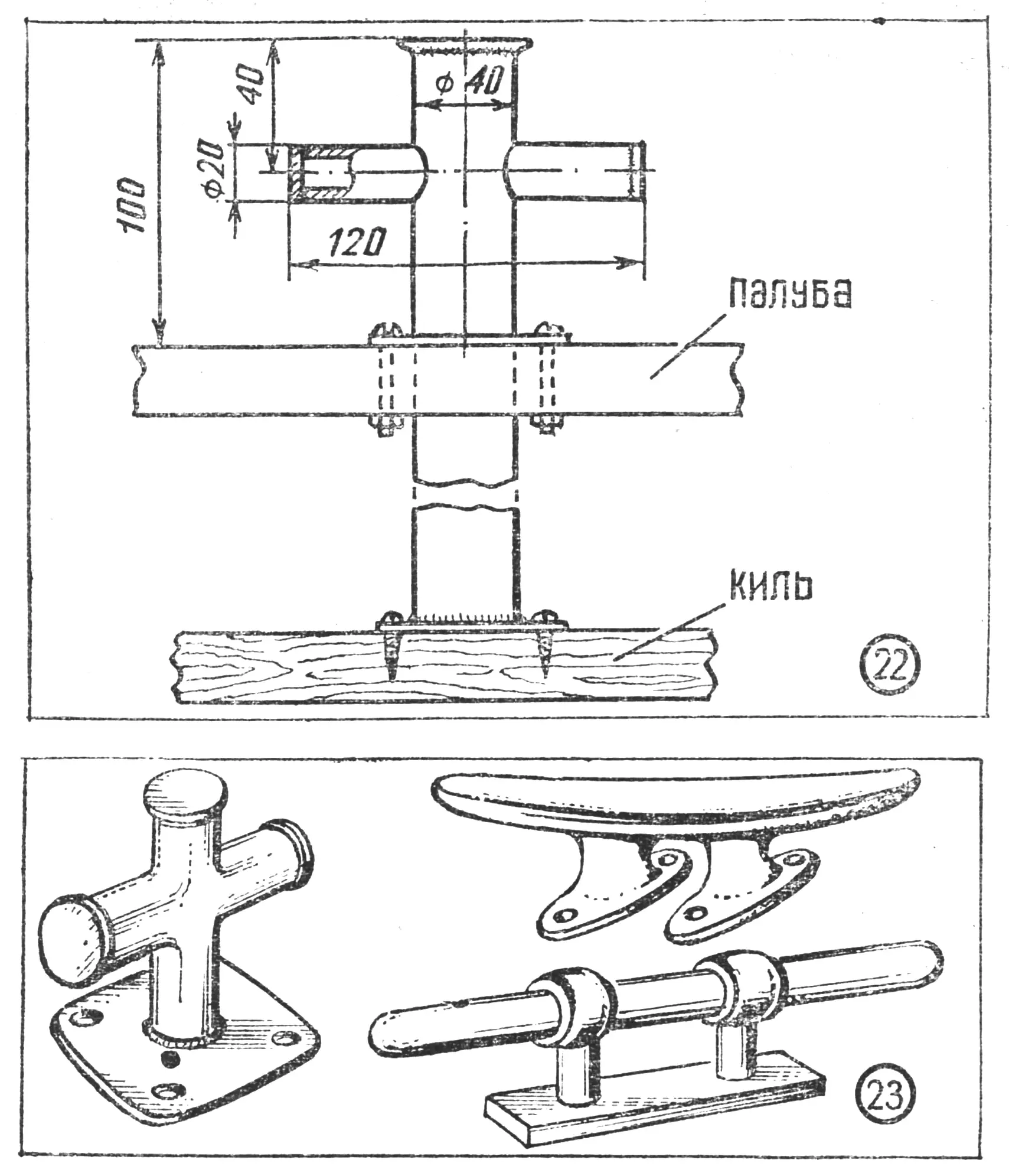
Fig. 23. Bollard designs.
Bitts and bollards are used for securing mooring lines. A bitt is a stout metal or wooden post fastened both to the keel and to the vessel’s deck (Fig. 22). This fitting is also used for towing. Bollards (Fig. 23) are usually bolted to elements of the deck framing.
We do not claim to give a complete description of all fittings used on modern sailing craft. Here we have presented only well-established designs used mainly on tourist sailboats.
“M-K” 9’79, V. YEVSTRATOV, engineer
Recommend to read
 BELKIN TRICKS
They say that squirrels dry mushrooms and berries — stock for the winter, — knots stringing them on trees. Don't know how true this is, but nevertheless it is this simple principle I... Automatic bee feeder and waterer
When I leased three apiaries with the right to buy them out, I realized how difficult it is to maintain a large number of bee colonies. I solved some of the problems with a feeder-drinker,...
