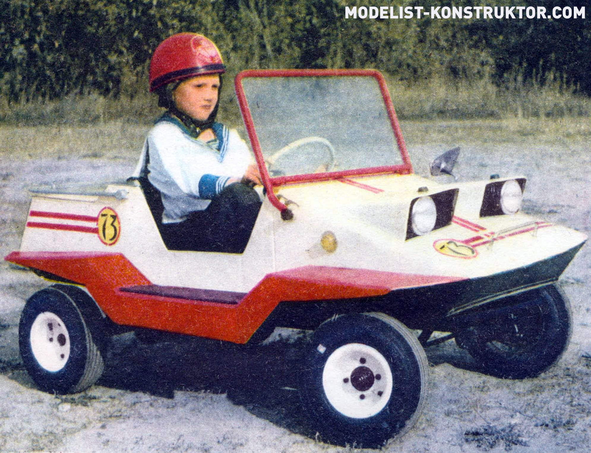
The “Druzhok” microcar is a car… for kids. It was created in the experimental modeling and design laboratory of the Young Technicians Club of the Novosibirsk Academic Town. Despite its small size, it has everything like a real car: engine, gearbox, driveshaft, closed rear axle with differential and other components.
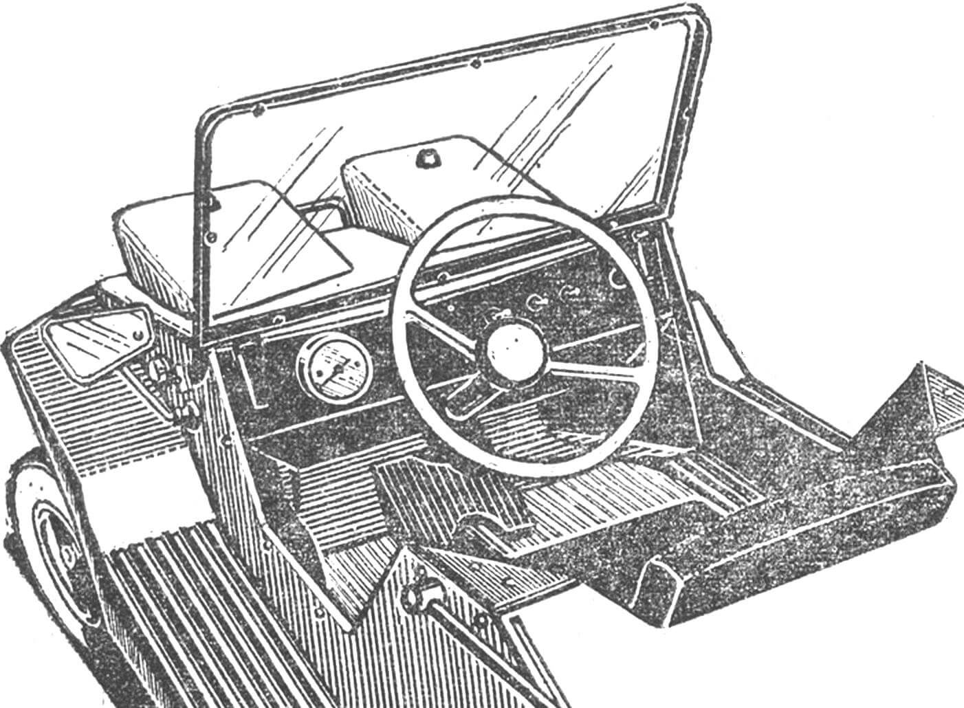
The open body is very compact and is intended only to protect the young driver from rotating parts and splashes when driving on a wet road. The body has a soft seat for the driver, control levers, an instrument panel and a steering wheel (Fig. 1). All this is installed on the car chassis and is not connected to the body.
By unfastening the two locks installed on the dashboard, the body can be lifted and free access to the engine can be obtained.
To remove the body, you need to unscrew two bolts at the back, which are the body hinge axles. The car body is made of cold-rolled steel sheet with a thickness of 0.7 mm. The shape of the car is strict and straightforward. This solution makes it easier to manufacture the machine and does not require special equipment.
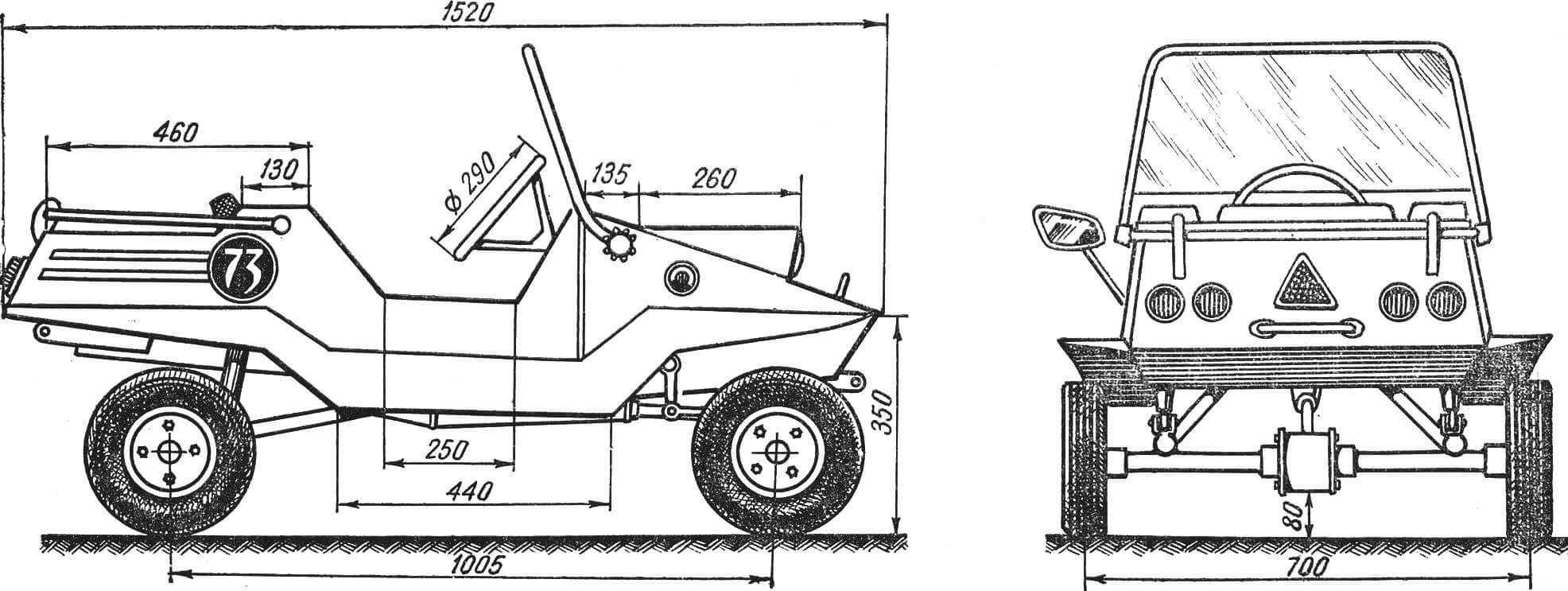
On the bevel of the hood, two headlights from a Ø 95 mm moped are installed in the “radiator” grilles, and at the rear there are turn indicator lights and brake lights. Two direction indicators are located on the sides of the front part of the body.
The car is equipped with fenders – mud flaps with running boards covered with a rubber mat. If necessary, the windshield can be placed on the hood of the body and secured with locking locks.
The body is painted with white nitroglyphthalic enamel, the wings of the car are bright red, with this body silhouette, these two colors are successfully combined and give the car an elegant look.
The rear of the car is made in the form of an open trunk, it is finished with a chrome lining – molding and a polished duralumin handrail.
The instrument panel is painted black, it has a speedometer, a signal light, and three toggle switches: ignition on, headlights on, signals on, turn on. An additional toggle switch under the shield is used to switch from direct current to alternating current when starting the engine.
On the panel there are two body fastening locks and an audible electric signal button (see Fig. 1).
Electrical wiring is mounted on the chassis and inside the body, ending with a six-pin connector. This connector connects the chassis wiring to the body electrical system. The connector is installed inside the instrument panel.
The chassis of the Druzhok car includes a steel tubular frame consisting of two longitudinal spars and five cross members. Total frame length 1240 mm. The frame is shaped like a trapezoid, widened at the rear. Crossbar dimensions: rear – 580 mm, front – 370 mm. Welded frame made of pipe Ø 20 mm.
An engine mounting bracket with three eyes is installed at the front of the frame. The engine is mounted across the frame using bolts. Two fingers are welded at the upper ends of the bracket for installing front suspension shock absorbers.
Behind the third cross member, a U-shaped bracket for attaching the instrument panel is welded to the top of the frame; it also serves as the front support of the body.
Behind the fifth cross member, two brackets with brackets are welded to the upper part of the side members on the right and left sides, in which there are holes at the ends for bolts for fastening the rear axle suspension elements.
Four eyes are welded to the bottom of the fourth cross member for attaching the rear suspension pendulums (Fig. 2).
In the corner, on the left, on the back of the frame, a box is welded for installing the battery.
The front axle consists of two transverse rockers in the form of right triangles, welded from a steel pipe Ø 20 mm. The axles of the steering knuckles of the front axles are welded at the corner vertices. Near the trunnions there are welded brackets with holes for the bolts for fastening the front shock absorbers. In the pipe, which is the leg opposite the apex of the angle, two bronze bushings are pressed into the trunnion, into which the bolts securing the rockers to the frame plates pass (Fig. 3).
Steering gear. The steering knuckles of the front axles are installed in the rocker axles. The axle has hubs that rotate on closed ball bearings. They are secured with a nut and cotter pins. The hubs have four studs on which the wheel disc is attached.
A longitudinal rod lever is welded on the left steering knuckle, which is connected to the bipod of the steering mechanism, which has a gear ratio of 1:3. Both steering knuckles are connected to the transverse rod by means of ball joints. Thanks to these rods, the wheels turn synchronously.
The rear axle has a prefabricated crankcase consisting of a steel welded ring with a seat welded into it for the shank bearings. The bearings contain the driveshaft shank. On both sides, flanges with sleeves for axle shafts are pressed to the ring using five through bolts. Ball bearings are pressed into recessed sockets on both sides of each sleeve. Steel axle shafts with splines at the ends rotate in the sleeves on bearings. The inner ends of the axle shafts fit into the splined bushings of the rear axle differential; the outer ends, extending from the sleeves into the wheel hubs, are secured with a nut and cotter pins.
The rear axle is suspended on two independently swinging pendulums. The front part of the pendulums is fixed in the frame lugs similar to the mounting of the front axle rockers. The rear part has pins that fit into bushings welded on top to the rear axle housing sleeves. The pins are secured with nuts and cotter pins, and are installed freely in the bushings so that on uneven roads the rear axle can have angular movements in the transverse plane.
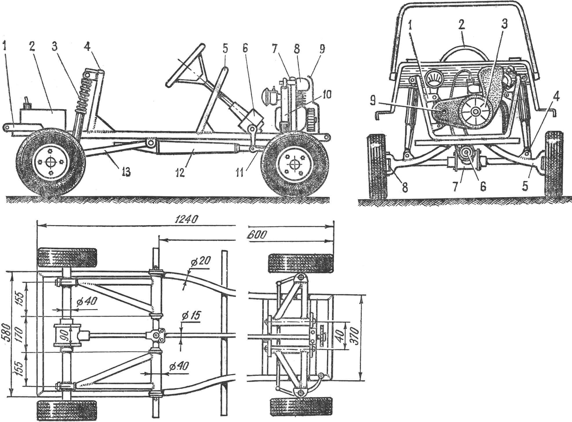
1 — body hinge bracket; 2 — gas tank; 3 — spring suspension; 4 — suspension mounting bracket; 5 — U-shaped body mounting arch; 6 — steering mechanism; 7 — bracket for fastening the front spring suspension; 8 — engine; 9 — cooling fan casing; 10 — spring suspension; 11 — longitudinal steering rod (conventionally shown on the right); 12 — exhaust noise muffler; 13 — rear suspension pendulum.
Rice. 4. Front view with body removed:
1 — bracket with eyes; 2 — steering wheel; 3 – fan; 4 — suspension mounting eye; 5 — front suspension rocker; 6 — driveshaft sprocket; 7 — differential housing; 8 — pivot pin, 9 — crank ratchet.
The pendulums are made of Ø 20 mm pipe. The rear axle is attached to the frame through spring shock absorbers using lugs at the rear ends of the pendulum (see Fig. 3, 4.)
Engine. The Druzhok car is equipped with a two-stroke Sh-50 engine with a displacement of 49.8 cm3. For better cooling, an impeller is put on the crank shaft, which, rotating, drives a flow of cold air onto the air cooling fins of the cylinder and head. The crankcase cover is removed, the lower part of the protrusion is cut off so that the chain from the engine sprocket does not go back, like a moped, but down to the driveshaft sprocket (see Fig. 4).
The cardan shaft is made of steel 45 Ø 15 mm, its total length with the hinge is 1000 mm. At its front end there is a 21-tooth sprocket, which is secured to a key and tightened with a nut. Behind the sprocket there is an outboard sealed bearing on a bracket, which is screwed with two bolts to the front cross member. The second bearing is mounted on a bracket suspended from the third cross member. At the rear end of the shaft there is a cardan joint mounted on splines. Its other side is connected to the rear axle shank shaft by welding.
The general layout of the chassis and its main dimensions can be seen in Figure 3.
Control. On the Druzhok car, as on other cars, there are a number of control levers, which were mentioned earlier. We will focus on the features of managing “Druzhkoy”.
Usually the car is driven in the following way: with the engine running, press the clutch pedal, engage the gear, smoothly releasing the clutch pedal, while simultaneously increasing the speed. In our car this happens differently. The young driver does not need to perform such a complex manipulation, but only needs to simultaneously and smoothly press both pedals – the clutch and the gas. To stop, you need to release both pedals. There is no brake pedal on Druzhka. She confuses the young driver. Therefore, on the right side of the cab there is a handbrake handle, which is always at hand. The brake pad is pressed directly against the rubber of the wheel from above.
The power system includes: a gas tank (polyvinyl chloride canister), mounted on a metal bracket welded to the frame; the gas line connecting the fuel pump to the carburetor, and the carburetor itself. The gasoline pump from the Moskva outboard motor is diaphragm-type and operates from pressure fluctuations in the engine crankcase.
The electrical equipment on Druzhka is six-volt, combined, direct and alternating current. For better starting, the toggle switch connecting the battery to the ignition system is turned on.
When the engine starts running, the battery is disconnected, and the ignition system is switched to operation from Magdino using the same toggle switch. It also powers the lighting and signal lights on the go. When the engine is not running and parked, you can connect the battery.
VEHICLE SPECIFICATIONS
Dimensions, mm: length – 1520, width – 780, height – 800 (with the windshield down – 540); wheelbase – 1005, track – 700, wheel diameter – 290. Vehicle weight – 47 kg. Engine – Sh-50 with a displacement of 49.8 cm 3 , combined transmission to the rear wheels, with a cardan shaft. Speed: with limiter – 5-8 km/h, without limiter – 40 km/h. Electrical equipment – six-volt, combined, direct and alternating current. The body is all-metal, open single.
M. LARKIN
Recommend to read
 “DIMENSIONLESS” APRON
Under the heading "Tips from around the world" published the description of "quick" apron, which at the ends of the garters were fastened with hooks, not to tie them in a knot. I want to...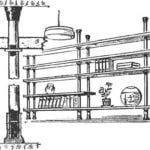 BETWEEN THE CEILING AND FLOOR
Every thing in the house requires a certain space. Updated your library, does kolichestvo aquariums — in any case before you arises the problem of their placement. To solve this problem...
