“Hello, dear editors! I have been prescribing M-K since 1969. I made a number of homemade projects based on the magazine’s drawings. I am, as they say, one hundred percent happy with them. I am especially pleased with the Amurchonok microtractor, which has become my reliable assistant. He will plow the ground and do the weeding, and hilling plants with him is not a problem. If it’s needed, it will do a great job at a construction site: it will transport whatever load is needed, and thoroughly knead the mortar (concrete).
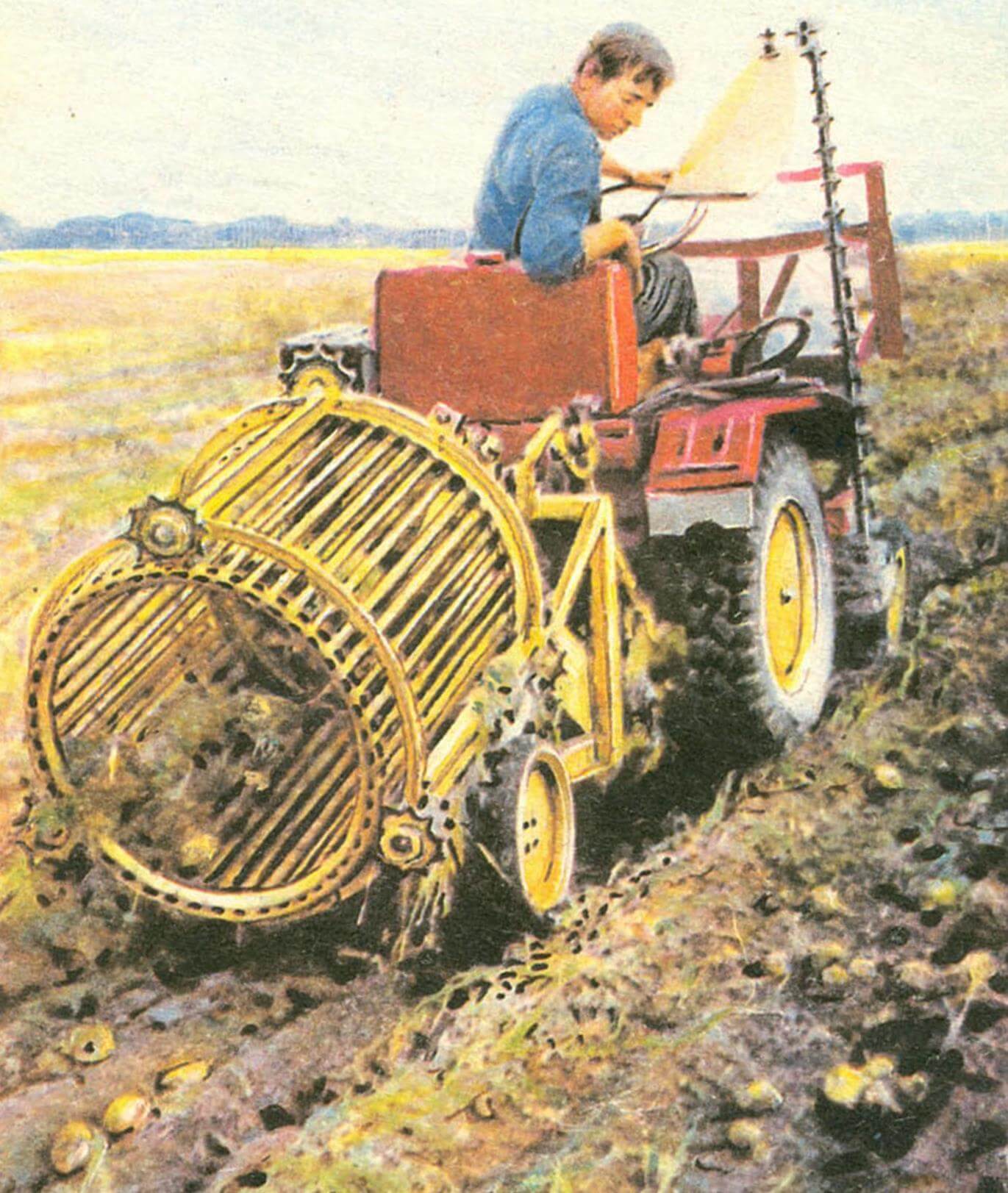
I would also like to equip my microtractor with a potato digger. The same as in the photo panorama “M-K” 5’89. If you publish the drawings, I’ll have time to do everything by the fall. To harvest potatoes on your plot no longer with the help of your grandfather’s shovel, but in a modern, mechanized way.
A. MARTYNOV, Lipetsk region.”
The editors received many letters with a similar request. The answer to them is the joint material published below by the author of the potato digger design that interested readers and a special correspondent of our magazine.
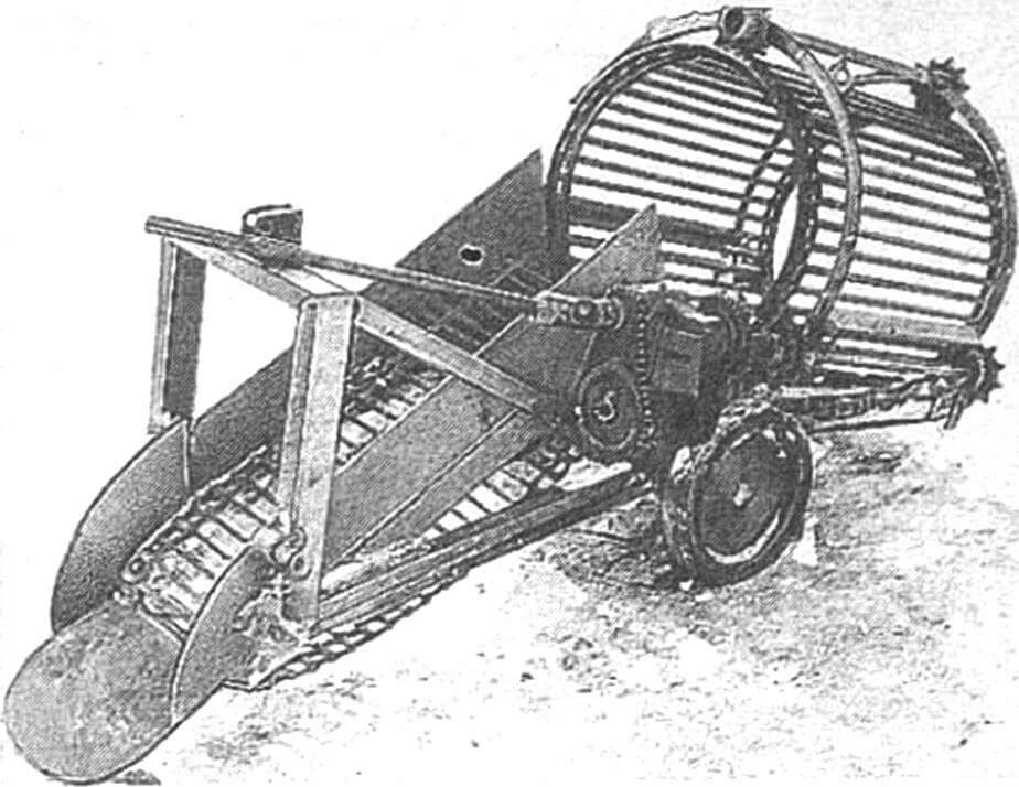
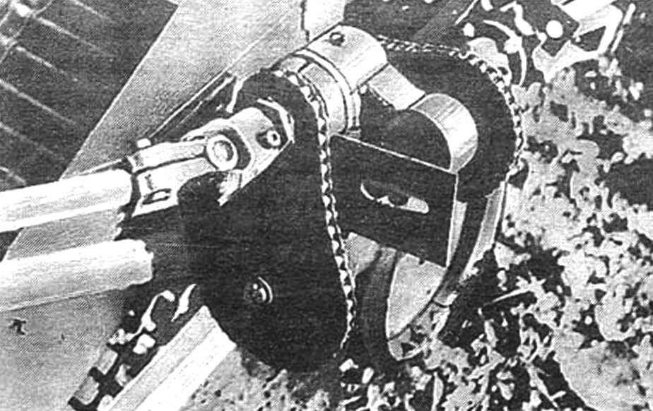
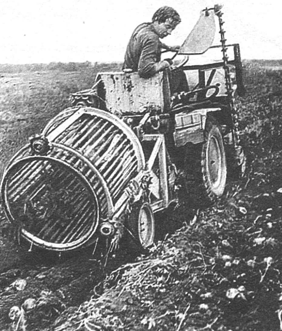
The proposed design is intended for mechanized potato harvesting. Moving behind the microtractor along the rows, this trailed unit “plows up” the soil with a shovel-shaped plowshare (to a depth of 100…120 mm), digging up tubers. Together with the soil and tops, they are thrown back onto the chain-and-rod conveyor of the elevator. The earth is sifted, and the potatoes, cleared of the remains of stems in a rotating drum, are placed in a row at the back. At the same time, the tops, twisted almost into a rope, lie down.
Losses and damage to the crop are minimized due to the thoughtfulness and reliability of the design, as well as the correspondence of the track width of the tractor used, the distance between the wheels of the potato digger’s support transport unit and the row spacing. In this case it is 2×560= 1120 mm and 560 mm (see figure).
The kinematics of the PKM trailed potato digger are based on cardan shafts (from the steering control of the T-40 tractor), two chain shafts (from the Tula-200 scooter), two chain-bar shafts (based on the roller chain for agricultural machines PRD-38 – for the elevator and the cleaning drum ) transmissions, as well as an angular gearbox (from the PK-1.6A pick-up stacker with i=1:1). The torque comes from the power take-off shaft of the tractor itself. An ordinary transport trolley with composite wheels was taken as an independent support-transport unit.
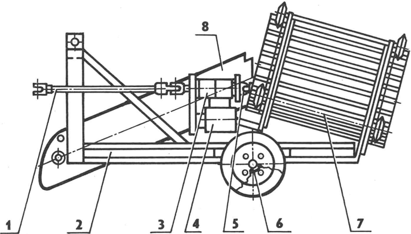
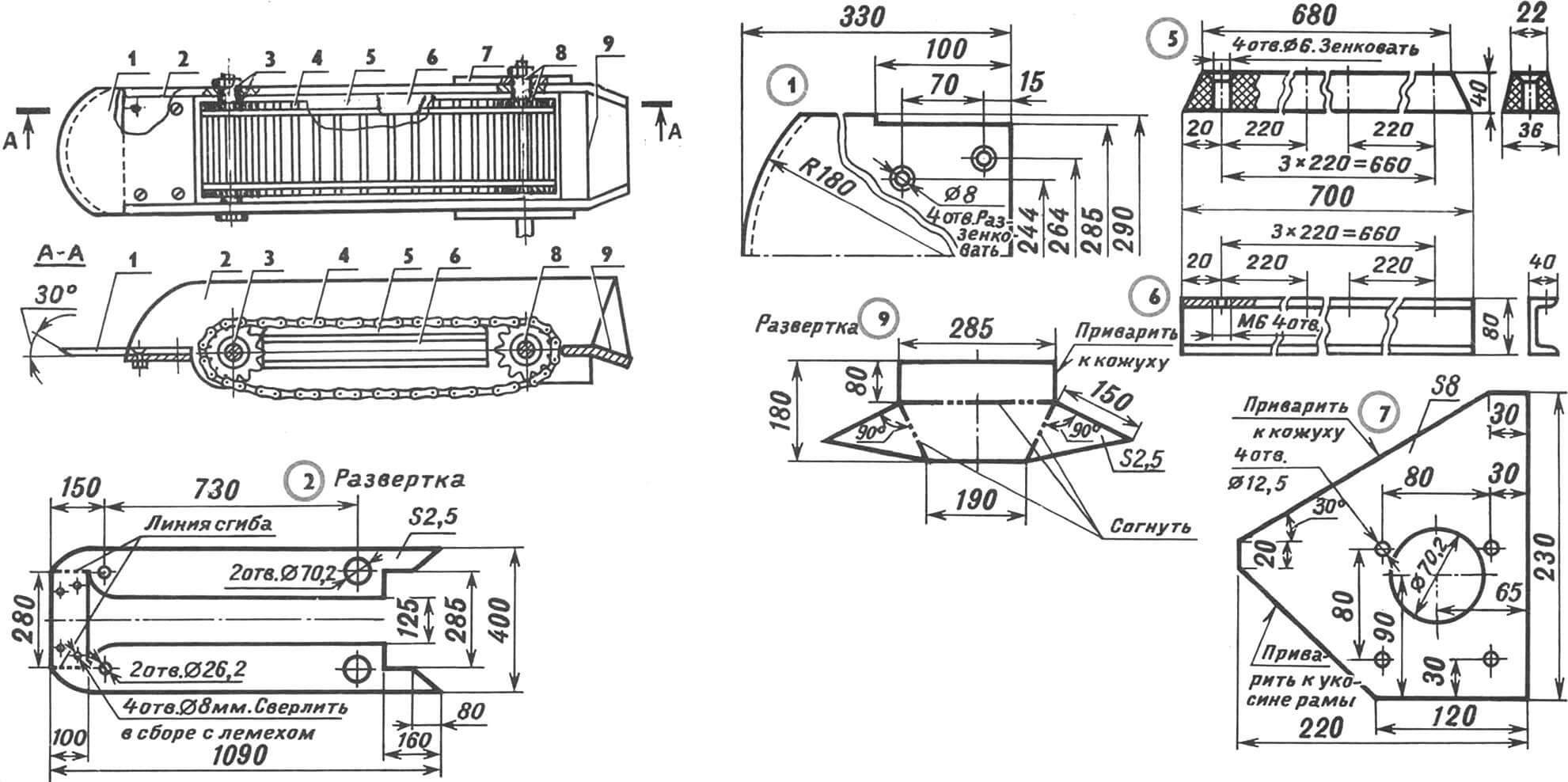
1 — PKM drive cardan shaft, 2 — base frame, 3 — reduction unit, 4 — angular gearbox (from the pick-up stacker), 5 — cardan shaft of the cleaner drum drive, 6 — support-transport unit, 7 — cleaner drum , 8 — chain-bar elevator with a ploughshare.
The sprockets used are standard ones with a number of teeth equal to 9.14 (from agricultural machinery) and 17.38 (from a motor scooter). True, the hubs of Z1 and Z4 had to be slightly altered, and Z6, Z7, Z11 (Z61, Z71, Z111) had to be mounted on single-row radial ball bearings with a seal of type 180,000.
But everything, naturally, will be much simpler if you can get the corresponding parts from a decommissioned serial potato harvester. The elevator conveyor is somewhat shortened in width. The tubes are removed from him. And they ensure that the speed of movement of the chain-bar belt exceeds the speed of creep of the bush being dug out with a ploughshare by the amount you need. As for the trays available in an industrial potato harvester, their installation in the PCM design (between the drum and the elevator) is not provided: the complication in this case can be considered inappropriate.
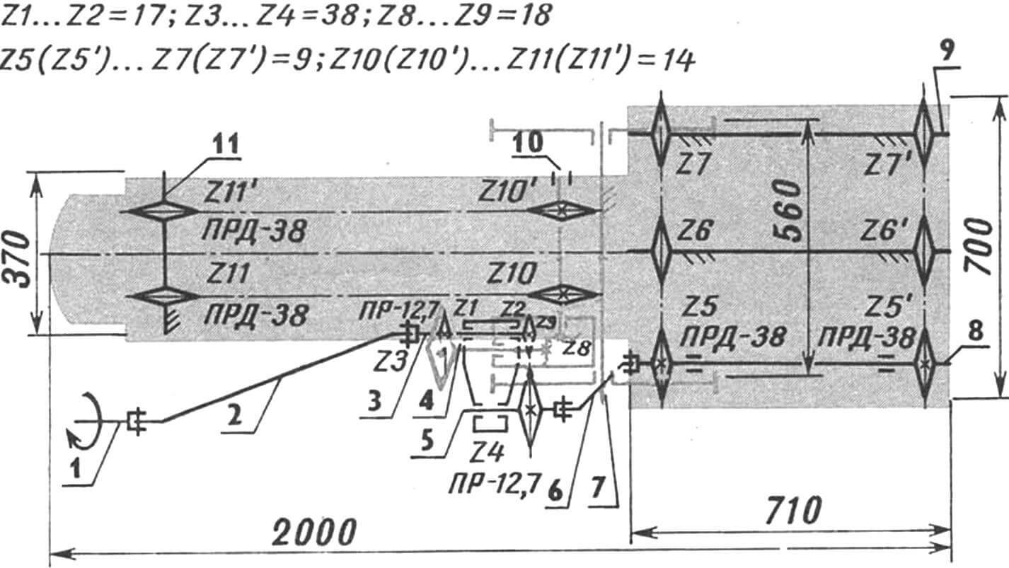
1 – power take-off shaft of a mini-tractor, 2 – cardan shaft of the PKM drive, 3 – input shaft of the reduction unit, 4 – input shaft of the angular gearbox (from the PK-1.6A pick-up stacker), 5 – output shaft of the reduction unit, 6 – gear cardan (from the steering control of the T-40 tractor), 7 — support transport unit (based on the transport trolley), 8 — input shaft of the cleaning drum, 9 — axis of the “squirrel wheel” sprockets (2 pcs.), 10 — elevator drive shaft, 11 — axis of the sprockets of the chain-rod conveyor.
The potato digger is assembled on a homemade base frame. The design here, as can be seen from the illustrations, is welded. Made from scraps of steel channel No. 8 using jibs (from channel No. 5), steel angle 63×40 mm and 8 mm plates.
The ploughshare is also made from a 5 mm plate (Steel 9ХС). But you can cut it out of a circular saw blade – it will work just as well. With four bolts with countersunk heads, the plowshare is attached (therefore, it can be replaced if necessary) to the rigid casing of the elevator and tightened with nuts. The oval sharpening (at an angle of 30°) allows this working element to dispense with large depths. After mechanized hilling, it is often quite sufficient that it does not go beyond 100…120 mm. In this case, tuber cuts are almost completely eliminated.
It is possible to change the tilt of the elevator (and therefore the “angle of attack” of the plowshare) by varying the place where the casing is attached to the base frame (not shown in the illustrations), as well as fixing the reduction unit.
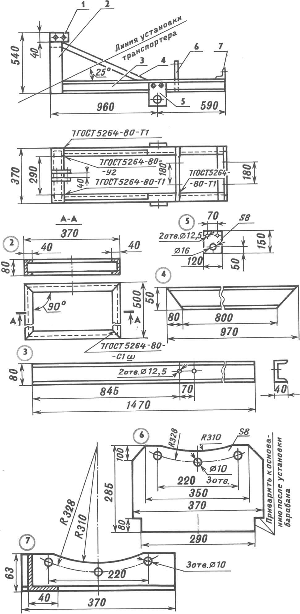
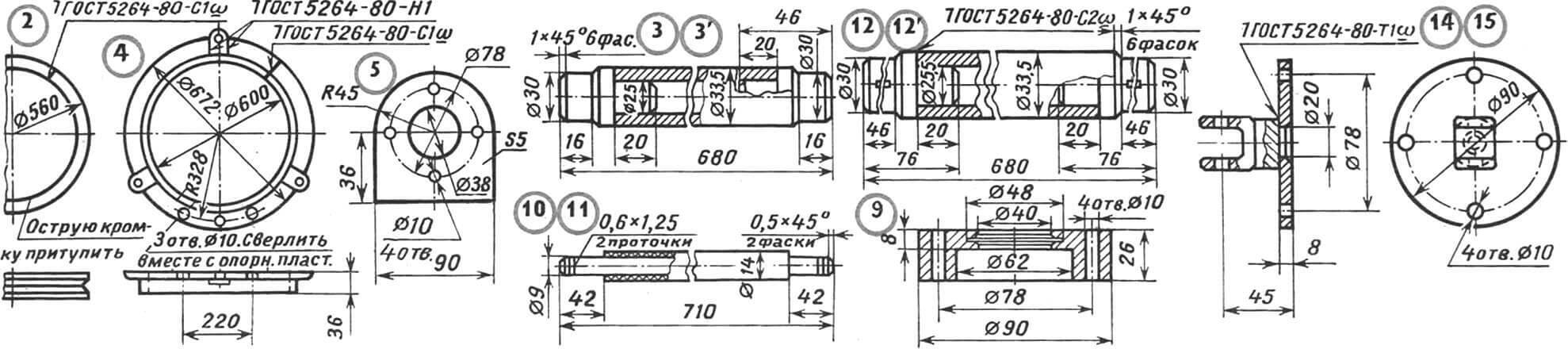
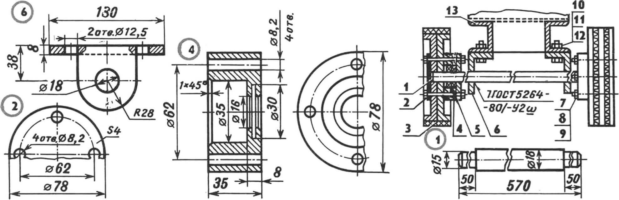
1 — suspension plate (piece of strip 80x40x8 mm, St3, 2 pcs.), 2 — suspension strut (steel channel No. 8), 3 — spar (steel channel No. 8, 2 pcs.), 4 — jib (steel channel No. 5 , 2 pcs.), 5 — mounting plate of the support-transport unit (St3, 2 pcs.), 6 — riser of the cleaning drum (8-mm steel plate, St3), 7 — rear support cross-member (steel angle 63×40 mm).
The design of the latter (see figure) is homemade. It consists of cylindrical housings rigidly connected to each other: a bushing and a cup made of Steel 30. In them, drive and driven shafts made of Steel 45 with sprockets mounted on feather keys rotate on ball bearings.
As already noted, the hubs of the sprockets (Z1=17 and Z4=38) are welded. The technology for manufacturing such ones has already been covered in sufficient detail by the magazine (see, for example, “M-K” 5’91). Moreover, as a hub for 24, you can take a 25-mm section of reinforced steel water and gas pipe 33.5×4.
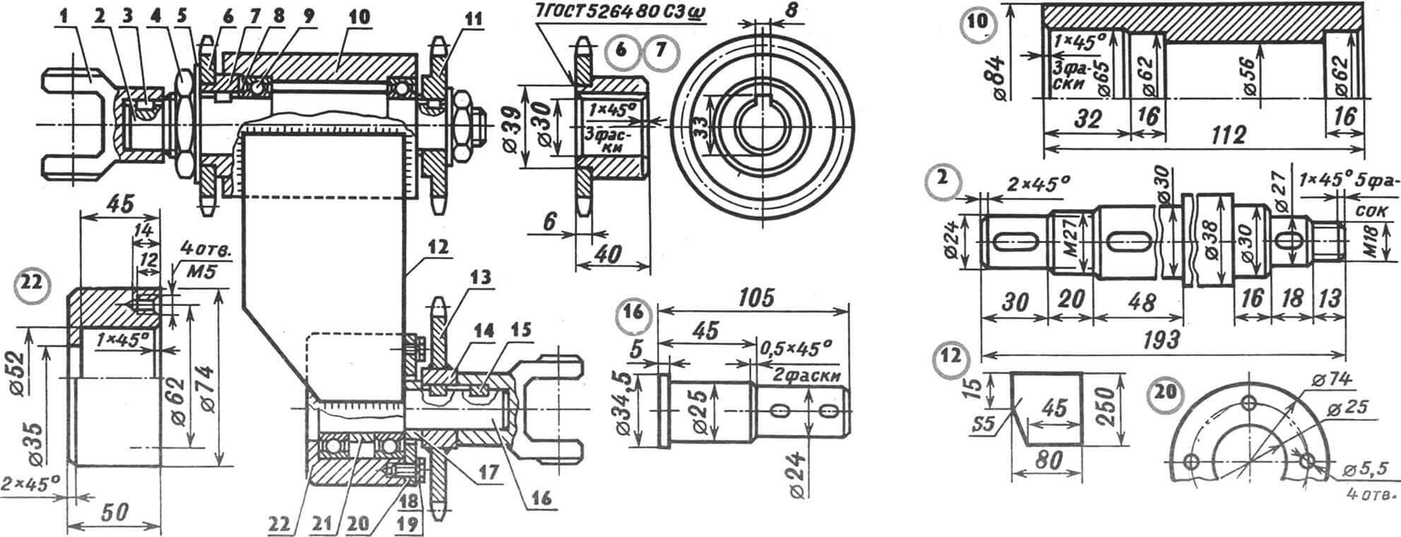
1 — cardan shaft fork (from the steering control of the T-40 tractor, 2 pcs.), 2 — drive shaft (Steel 45), 3 — prismatic key 6x6x12 mm, Steel 45, 3 pcs., 4 — M27 nut (2 pcs. .), 5 — washer (2 pcs.), 6 — welded sprocket Z1=17 (from the Tula-200 scooter), 7 — hub (Steel 45), 8 — thrust ring (2 pcs.), 9 — ball bearing 180 206 with seal (2 pcs.), 10 — housing-bushing (Steel 30), 11 — sprocket Z2=17 (from a scooter), 12 — welded plate (5 mm St 3, 2 pcs.), 13 — sprocket Z4=38 (from the Tula-200 scooter), 14 — hub hub (Steel 45), 15 — prismatic key 5x5x10 mm (Steel 45, 2 pcs.), 16 — driven shaft (Steel 45), 17 — ring thrust (St. 3), 18 — M5 screw (4 pcs.), 19 — Grover washer (4 pcs.), 20 — cover (St. 3), 21 — spacer sleeve (St. 3), 22 — glass body (Steel thirty).
Perhaps the most difficult thing to manufacture in a “home workshop” will be the cleaning drum. It is based on two 1790 mm PRD-38 roller chains. More precisely, 94 links located not on their axes, but at the ends of 47 rods with a protective (so as not to accidentally damage the tubers) shell in the middle. To tension the resulting “squirrel wheel” and give it a certain strength, two disks are used, bent from 1760 mm sections of a pre-released 20×20 mm steel angle. Moreover, welding is performed here after tensioning the chain.
But you can get by with two ready-made wheel rims from a teenage bike, if you happen to have them on hand. The “squirrel wheel” is pulled to the bottom using clamps and welded element by element. To obtain even greater rigidity, the structure can be strengthened by welding rods (10…12 mm) of corrugated reinforcement.
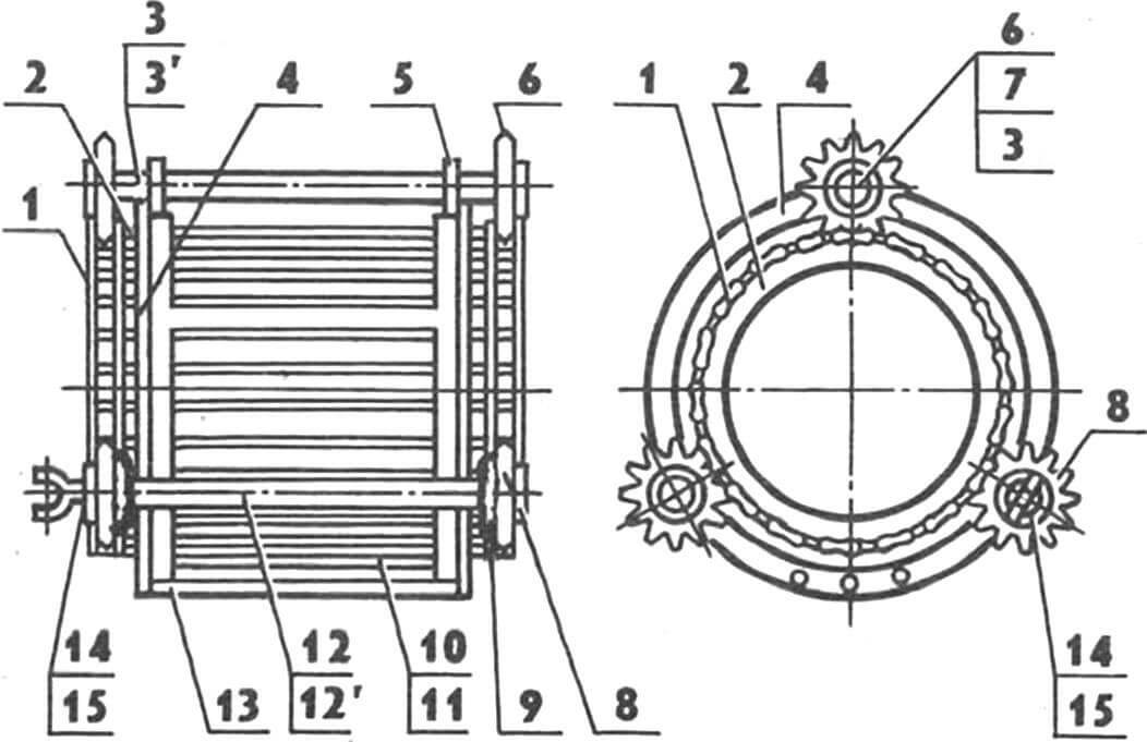
1 — 1790 mm roller chain PRD-38 (2 pcs.), 2 — chain tension disk (from a 1760 mm piece of angle 20×20 mm, 2 pcs.), 3 — end cap of the welded axis of the “squirrel wheel” sprockets (Steel 45, 4 pcs.), 31 — base of the welded axis of the “squirrel wheel” sprockets (628 mm section of water and gas pipe 33.5×4, reinforced, 2 pcs.), 4 — support disk (steel angle 36×36 mm, bent , 2 pcs.), 5 — support plate (St 5, 6 pcs.), 6 — sprocket with a seat for a ball bearing (4 pcs.), 7 — ball bearing 180 206 with seal (6 pcs.), 8 — input sprocket ( drive) shaft (2 pcs.), 9 — bearing cup support (Steel 30, 2 pcs.), 10 — “squirrel wheel” rod (47 pcs.), 11 — protective shell (piece of rubber hose, 47 pcs.) , 12 — end of the welded shaft (Steel 45, 2 pcs.), 121 — base of the welded shaft of the cleaning drum (568-mm piece of 33.5×4 reinforced water-gas pipe), 13 — spar (588-mm piece of 36× steel angle 36 mm, 3 pcs.), 14 — flange (St. 3), 15 — cardan shaft fork (from the steering control of the T-40 tractor).
The “squirrel wheel” rotates, sandwiched between sprockets located on two axles and on a shaft (secured to the support disk using six welded plates). Moreover, both the axles and the shaft are composite. They are made using the same technology and represent a water and gas pipe of the appropriate diameter, with welded ends made of Steel 45 on both sides.
1 — ploughshare (made from a circular saw blade or 5 mm Steel 9ХС), 2 — casing (2.5 mm St3), 3 — input axis assembly of a chain-rod conveyor), 4 — 1670 mm conveyor belt (based on a roller chains PRD-38, 2 pcs.), 5 — runner (Ftoroplast-4D, 2 pcs.), 6 — structural reinforcement beam (steel channel No. 8, 2 pcs.), 7 — support (St 3, 2 pcs.) , 8 – drive shaft assembly, 9 – gusset (St. 3).
Both axes are stationary. Welded to support plates. But the driven sprockets on the axles rotate, since the sleeve of each is mounted on the outer race of the ball bearing 180 206. Moreover, the axles are welded to the support plates after pressing the ball bearings with the sprockets and adjusting their position. As for the shaft, it rotates on bearings 180 206. And the drive sprockets rotate with it, causing the drum itself to rotate. It is attached to the “input” drive sprocket with four screws. M10 flange with a cardan fork welded to it.
The elevator drive shaft has a similar design. The Z=14 sprockets rotate with it, being seated on parallel keys 8x7x45 mm and clamped from the sides using spacer rings and a bushing made from sections of seamless cold-drawn steel pipe. The bevel gear is welded to the shaft. A pair of bearings is firmly seated in the gearbox housing; The gearbox housing is fastened to the support using M12 bolts.
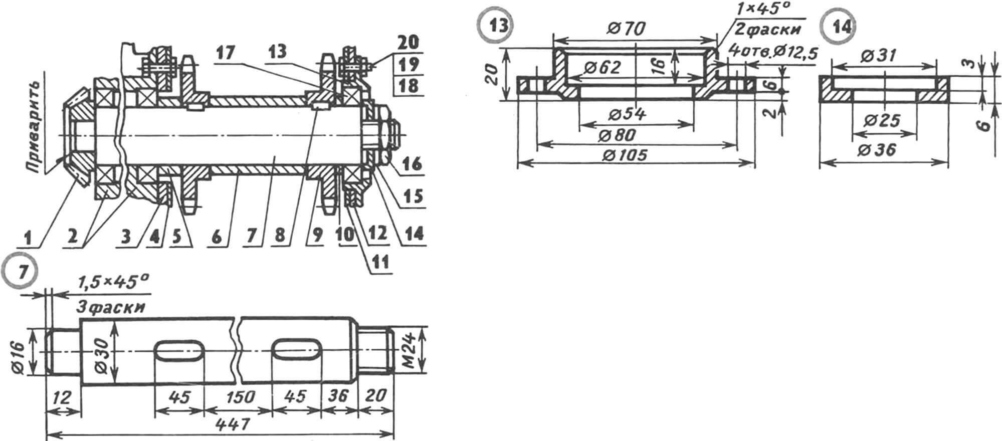
1 — bevel gear Z=18 of the bevel gear, 2 — bearing assembly of the gearbox, 3 — support for the left side of the casing, 4 — left side of the casing, 5 — spacer ring (30 mm piece of 38×4 steel seamless cold-drawn pipe), 6 — bushing (145-mm piece of pipe 38×4 seamless cold-drawn steel), 7 — elevator drive shaft (Steel 45), 8 — prismatic key 8x7x45 mm (Steel 45, 2 pcs.), 9 — sprocket Z=14 (from agricultural machinery, 2 pcs.), 10 — closing ring (17 mm piece of 38×4 steel seamless cold-drawn pipe), 11 — right side of the casing, 12 — support for the right side of the casing, 13 — cup-bearing housing (St. 5), 14 — cover pressure bearing (St 5), 15 — Grover washer, 16 — M24 nut, 17 — ball bearing 180 206 with seal (3 pcs.), 18 — M12 bolt (8 pcs.), 19 — split washer (8 pcs.), 20 — M12 nut (8 pcs.).
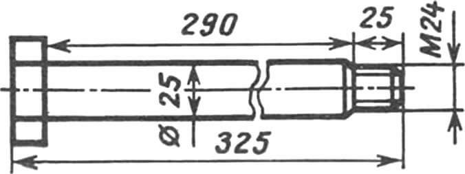
The input axis of the chain-bar conveyor resembles a bolt with an M24 thread at the end. The axle is inserted into the housing hole on the left side. Then the spacer sleeve is put on, followed by bearing 180 205 with a Z=14 sprocket pressed onto its outer race. The intermediate sleeve, the second bearing with an asterisk, and the spacer ring are put on. And then the axle is inserted into the hole in the casing on the right side. The fastener is completed with an M24 nut and washer.
1 – axle (Steel 45), 2 – flange (St 5, 2 pcs.), 3 – wheel assembly (from the transport trolley, 2 pcs.), 4 – bearing housing (Steel 20, 2 pcs.), 5 – ball bearing 202 (4 pcs.), 6 — suspension support (from a 130 mm piece of steel angle 60×40 mm, 2 pcs.), 7 — M8 nut (8 pcs.), 8 — split washer (8 pcs.) , 9 — M8 bolt (8 pcs.), 10 — M12 bolt (4 pcs.), 11 — Grover washer (4 pcs.), 12 — M12 nut (4 pcs.), 13 — PCM base frame.
Chain-bar tape is like a modified (stretched) “squirrel wheel”. It is made on the basis of two 1670 mm PRD-38 roller chains. But there are already slightly fewer rods here (44 pieces). On top of that, they are also shorter than the “squirrel” ones: 275 mm. For better sliding of the tape along the slider, the latter is made of fluoroplastic-4D. It is secured to the structural reinforcement beam using four M6 countersunk screws. Located on the sides of the elevator casing, both sliders serve as a supporting surface for the chain links and protect it from damage.
Now all that remains to consider is the support and transport hub. But it is quite simple in design, and is unlikely to cause any difficulties in manufacturing. The dimensions and fastening of parts are clear from the illustrations.
Six years of experience in operating the PKM potato digger has shown the high reliability of this design, and revealed its advantages in comparison with, say, a drum-screw one. And the kinematics turned out to be so successful that the Krasnoyarsk Combine Harvester Plant decided to take it as a basis when developing a mass model. But for some reason I don’t see it on sale. But we are, as they say, no stranger to such sluggishness among factory workers.
E. SVIRIDOV, Krasnoyarsk, N. KOCHETOV, our specialist. corr.
Recommend to read
 BY “DIMLY”
As a rule, in all our homes — three-wire system on the chandeliers, combined with the series switches, providing three options of illumination. For patipanno chandeliers — two, three and... WILL INCLUDE A KETTLE ON THE LASER!
The convenience of wireless remote control (RC) is undeniable. You can use them, without getting up, and the most interesting channel to enable, and the hardware on it to adjust...
