UNMATCHED AVIATION

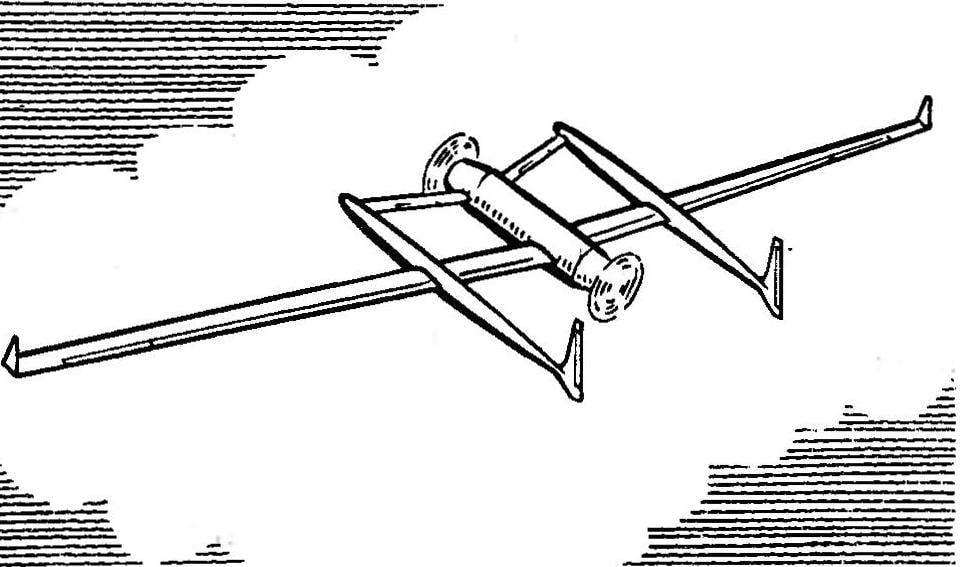
UNMATCHED AVIATIONToday we continue the theme begun with the publication of non-traditional polyopia supersonic fighter-interceptor MiG-25, the New development even more unusual in the choice of the prototype for the copy and overall design of the model. Today, it is about the reproduction in miniature of a legendary airplane “Voyager”, made in 1986 by flying non-stop around the globe. I hope that ego of publications will contribute to the revival of some extinct interest to the class “school” sports polycopy. It should again be noted that Voyager, like the MiG-25, only a single instance of a large number of interesting prototypes, giving modelistica up at any level.

Despite the fact that the new cord polyopia were studied under a simplified “school” manufacturing techniques (design model designed in three versions: simple, more simple and… simplified “longer”), dimensions turned out unusual solid: wingspan scale 1:15, concerning the nature amounted to 2250 mm. Less than the microplane to do was pointless because the engines wouldn’t fit into the dimensions of the fuselage. However, further study of the project showed that especially the little things don’t need to. The dimensions of the bearing area of the model was in quite acceptable range. The same can be said about the total mass procopii, specific loads on the bearing surface and the unit a total power of the engines.
The first flight test of the car showed that it has a surprising volatility, after take-off easily even on one engine, and two with a mild wind performs steady flight at an angle of 45°, Seen in model execution that benefit from the ideas the designer of the Voyager Burt Rutan in the scheme of the aircraft record and led to excellent aerodynamic quality of the unit. Just note that even with accelerated “Juniors” polyopia fuel type CMD (without the amyl nitrate) flies at an average speed of 100 km/h, which increases the reliability of the demonstration of “45°”.
 
Central fuselage of the model
 
The Central fuselage of the model:
1 — modified compression Microdrive MK-17, 2 — steel screw MZ motor mount (to glue and epoxy in the cut in the wood holes recessed screw heads prior to installation, the left panel of the fuselage skin), 3 — power plate (Linden, aspen thickness 11 mm), 4 — upper stringer (Linden or pine with cross section of 4-11 mm), 5,7,11 — interior kit (basswood or pine cross-section 2×11 mm), 6 — scale spinner (aluminum), 8 — fuel tank (to glue in the cavities of the fuselage with the output through the left trim panel grubac drainage and filling), 9 — rear force plate (Linden, aspen thickness 11 mm), 10 — through the slot or tipped-MZ screw for fixing the control arms of, 12 — panel of the fuselage skin (Fanta thickness 1 — 1.2 mm), 13 — landing gear (wire OVS diameter 2.5 mm), 14 — brace stand (wire OVS 1.5 mm diameter), 15 — the lower stringer (Linden or pine cross-section SX 11 mm); a— the treatment area of the security plate before attaching the left side trim panel.


The left beam of the fuselage
 
The left beam of the fuselage:
. 1 — power plate (Linden or aspen with a thickness of 5 mm), 2 — stringers (Linden or pine with cross section of 3×5 mm), 3 — interior set (Linden or pine cross-section 2×5 mm), 4 — panel sheathing (plywood with a thickness of 1 mm or a cardboard with thickness of 0,5 — 0,6 mm), 5 — Central power plate (Linden or aspen with a thickness of 5 mm), 6 — landing gear (wire OVS diameter 2.5 mm), 7 — brace stand (OVS wire diameter 1.5 mm; strut Assembly to glue the epoxy to the winding wire, a thin cotton thread), 8 — Kiel (Linden or aspen with a thickness of 3 mm), 9 — rudder (together with the keel, after the profiling of the workpiece to separate the keel using a jigsaw; to hang when building models on pieces of aluminum wire with a diameter of about 1 mm); a — area of wedge-shaped thinning of the stringers.


End plates of the wing
 
End plates of the wing:
1 — plate (lip thickness 2-2,5 mm), 2 — bracket for wiring cords (plywood with a thickness of 2 mm; after installation, the short copper pipes to glue on the left console), 3 — wing, 4 — fairing transition from the wing to the plate (Linden).

 
The profiles of the bearing surfaces
 
Sections of the carrier planes:
A Central part of the wing, B — end section of the wing, stabilizer. (The design with the partial application of balsa.)
The method of calculation of the mass of wood planes on the example of the wing to the forehead of dense material and a tail from balsa (average density 0.2 g/CM1).


Record-breaking twin-engine twin aircraft
 
Record twin-engine twin aircraft”duck” Voyager design Burt Rutan.
 
 
A list of possible demonstrations for this copy of the single-mode plane-stayers is small. In any case, it is useful to provide a program of performances'”the maximum.” What can be enjoyed in the test flight? The simplest is a “conveyor belt” of flying on one engine (in accordance with the terms dereviane) and flying at an angle of 45°, which runs on two engines (as is known, in a record-breaking flight of the Voyager in the wind for a long time, threw in the flight mode on “the knife”!). With a little modification of engines to this list, you can add another control rod motors and the release and cleaning of the flaps. If desired, designers can try to solve the problem of cleaning of the landing gear. Note that there is one effective and more than simple and reliable solution mechanics of this site. However, secrets yet to reveal and will not offer to solve a similar problem yourself.
 
Total recruited six demonstrations. Crediting flight even in gusty wind mini-Voyager thanks to its. aerodynamics almost always performs on “ten”.
The figures show the most complex version of the design model based on partial use of balsa in the power circuit of the wing and stabilizer. Now this former scarce wood became available. The design of the fuselage and the beams can be monolithic. The Central fuselage vystragivaetsja from a piece of Linden or aspen with a thickness of about 5 mm, and after processing the workpiece in the sub zones glued 1 mm overlapped plywood. Beams are also cut from 3 to 4 mm Lastin Linden or aspen. All load-bearing plane (wing and stabilizer) vystragivaetsja from solid billets of the same wood, and without first selecting the mechanization of the wing and control surfaces of the stabilizer. In this performance polyopia after finish the Assembly will be indicated in the table the maximum mass.
 
The easier option alnobetula design with the same lining of the ends of the fuselage 1 mm plywood (the thickness of the blank of the fuselage should be equal to 8-10 mm, and the beams – 5 mm). However, then have trouble with the exterior model because the pores of the wood somewhat complicate the processing of the surface. Although, if you are able to buy the balsa in the right quantity, will not be big problems to stock up on a special film for covering a mini Voyager, in balsa and with a tight wrap
 
dry weight Prokopii in take-off condition is equal to approximately 800 — 900 g.
 
In all cases, the wing is split. To make the nodes of the connector, you can easily, therefore we do not give recommendations. Management — external simple type, with wiring cords under the front edge of the wing. Alignment is a fully equipped model should be in 10 — 15 mm in front of the Central section of the wing.
 
The new machine is equipped with engines MK-17, which cut off the excess weighty cooling jacket of a cylinder (shaped like a triangle with the corners in areas of mounting screws). In addition, in accordance with earlier publications in the “Modeller-designer” modificeres node of the carb and fixing the axis of the spool (the nozzle is made through and is used just like the MC-12B or”Rhythm”). Power —gas pressure taken from the crankcase through the set in his sock from the bottom fitting of the valve facing the cavity in front of the native bearing of the crankshaft. Propellers can be modified brand of the plastic (due to the increased weight they will provide easier starting), or homemade wood (these are more efficient in the air if done correctly). In any case, you need to check what will happen with the crankshaft rear pusher engine in its vietii into the crankcase, and if necessary, put wheel bearing, Besides, it is better to provide a propeller with a slightly increased pitch.
 
In conclusion, I would like to appeal to those who mastered the technology of making models from foam, followed by their tight tight wetmanski paper. Think about — perhaps this prototype and offer a copy for your hands?
 
V. TIKHOMIROV

Recommend to read

  • STEERING THE MACHINE WITH THE MEMORY BLOCKSTEERING THE MACHINE WITH THE MEMORY BLOCK
    It differs from steering devices based on electromagnets less weight, reliable fixation of steering, more traction and efficiency. The memory block machine provides a return of the...
  • “MOTORCYCLE” OF AN AGRONOMER“MOTORCYCLE” OF AN AGRONOMER
    This ultra-light vehicle - a kind of “motorcycle” on an air cushion - was built in Bataysk at the city SUT. Its advantages are simplicity of design, high maneuverability and quite...