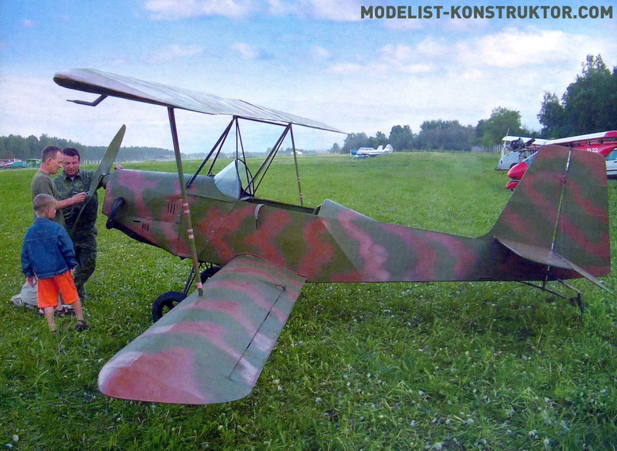
Building my own plane has been my dream since childhood. However, I was able to implement it not so long ago, although I paved the way to the sky in military aviation, and then on a hang-glider. Then he built an airplane. But the lack of experience and knowledge in this matter also produced a corresponding result – the plane never took off. The failure did not exactly discourage the desire to build aircraft, but it cooled the ardor thoroughly – a lot of time and effort had been spent. And what helped revive this desire was, in general, an incident when the opportunity arose to inexpensively purchase some parts from a decommissioned An-2 aircraft, more popularly known as the “Corn Man”. And I only purchased ailerons with trim tabs and flaps. But from them it was already possible to make wings for a light biplane aircraft. Well, the wing is almost half the plane! Why did you decide to build a biplane? Yes, because the aileron area was not enough for a monoplane. But for a biplane it was quite enough, and the wings from the An-2 ailerons were even shortened a little. Ailerons are located only on the lower wing. They are made from twin aileron trimmers of the same An-2 aircraft and are suspended on the wing on ordinary piano hinges. To increase the efficiency of aircraft control, wooden (pine) triangular slats 10 mm high are glued along the trailing edge of the ailerons and covered with strips of covering fabric.
The aircraft was conceived as a training aircraft, and according to the classification it belongs to ultra-light devices (ultralights).
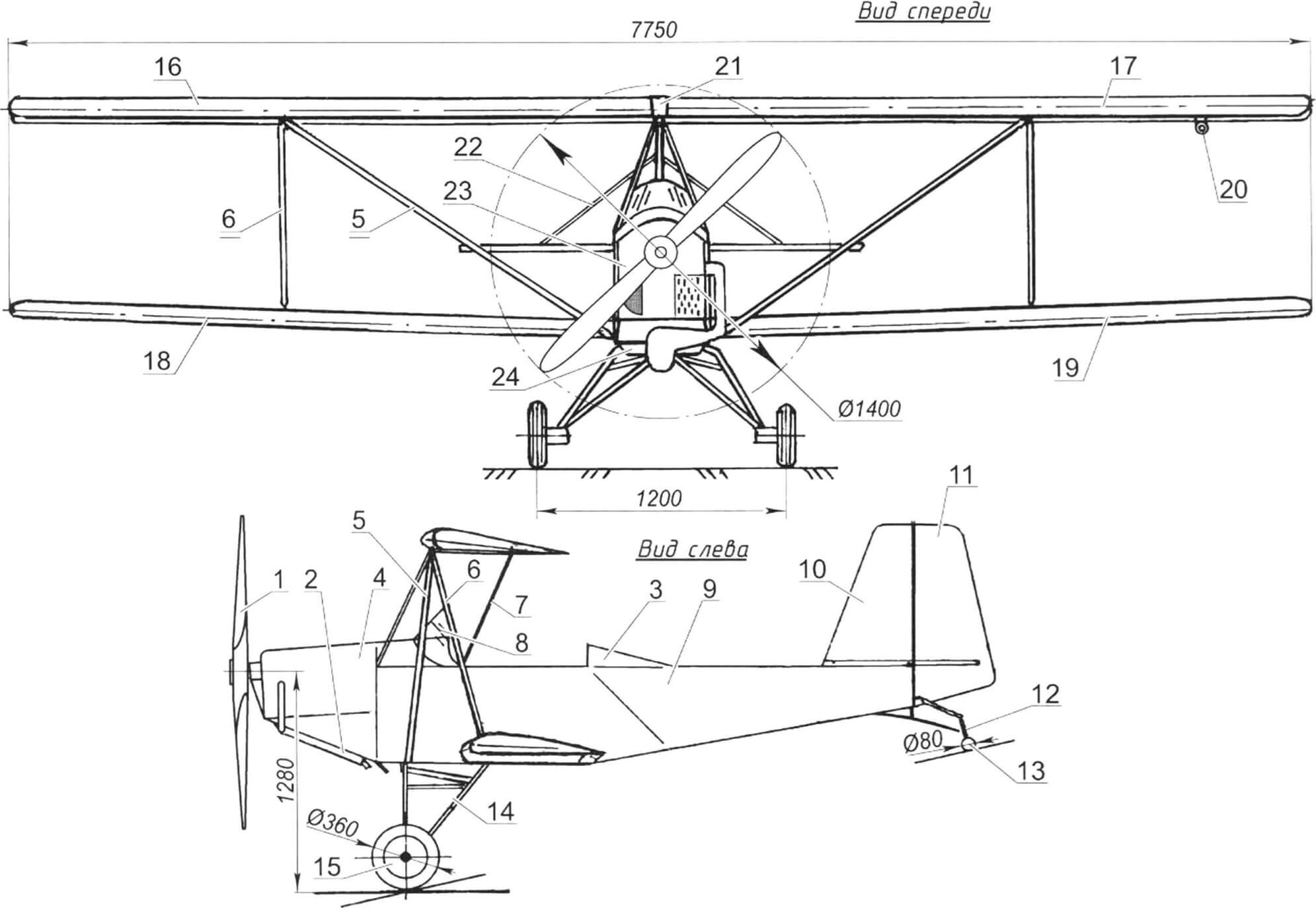
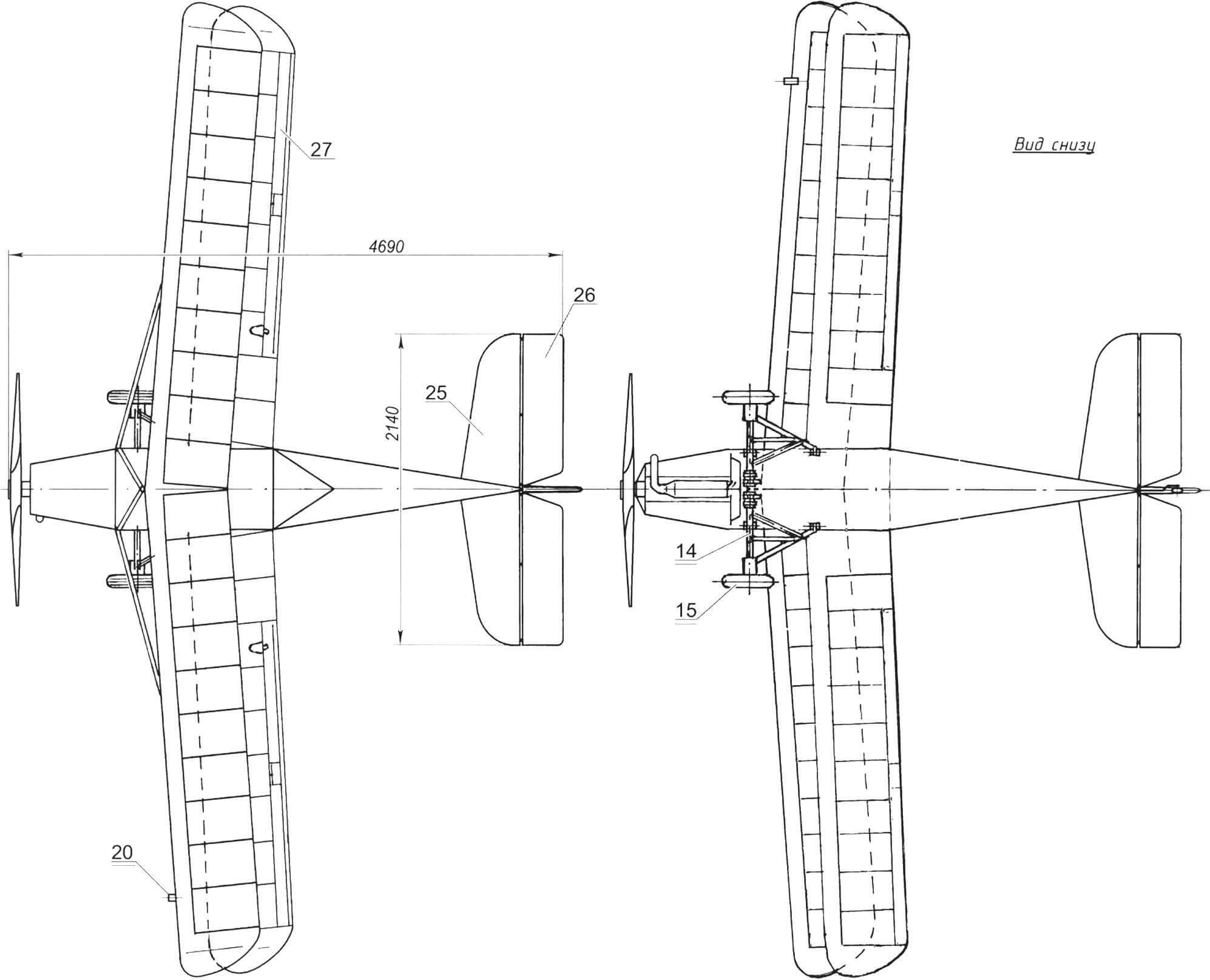
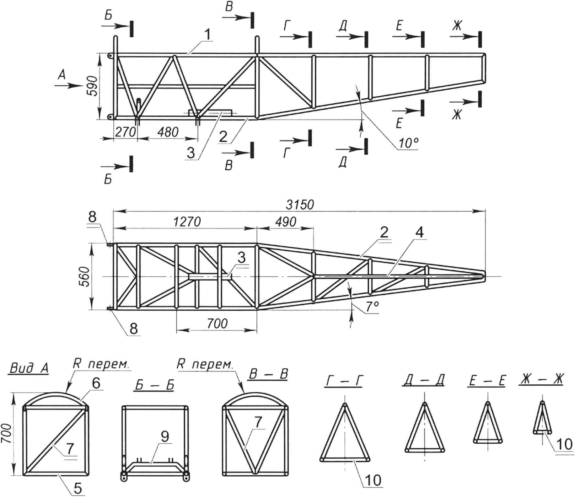
1 — propeller (two-bladed, monoblock, Ø1400, t = 800); 2 — muffler; 3 — cockpit fairing; 4 — hood; 5 — upper wing console strut (2 pcs.); 6 — stand (2 pcs.); 7 — pylon of the upper wing; 8 — transparent visor; 9 — fuselage; 10 – keel; 11 — steering wheel; 12 — tail support; 13 — tail steering wheel; 14 — main landing gear (2 pcs.); 15 — main wheel (2 pcs.); 16 — right console of the upper wing; 17 — left console of the upper wing; 18 — right console of the lower wing; 19 — left console of the lower wing; 20 — air pressure receiver; 21 — overlay for the joint of the upper wing consoles; 22 — stabilizer and keel brace (2 pcs.); 23 — engine hood with air intake; 24 — gas flap; 25 — stabilizer (2 pcs.); 26 — elevator (2 pcs.); 27 — aileron (2 pcs.)
By design, the aircraft is a single-seat, single-strut biplane with a tricycle landing gear with a steerable tail wheel. I couldn’t find any prototype, and therefore decided to design and build according to the classical scheme and, as motorists say, without additional options, that is, in the simplest version with an open cockpit.
The upper wing of the “Grasshopper” is raised above the fuselage (like a parasol) and fixed slightly in front of the pilot’s cabin on a support made of duralumin pipes (from the An-2 aileron rods) in the shape of an inclined pyramid. The wing is detachable and consists of two consoles, the joint between which is covered with a cover plate. The wing set is metal (duralumin), the covering is linen impregnated with enamel. The wing tips and root parts of the wing consoles are also covered with a thin duralumin sheet. The upper wing consoles are additionally supported by struts running from the attachment points of the inter-wing struts to the lower fuselage spars. The air pressure receiver is fixed at a distance of 650 mm from the end of the left upper wing console. The lower wing consoles are also detachable and are attached to the lower fuselage spars (on the sides of the cabin). The gaps between the root part and the fuselage are covered with linen (impregnated with enamel) fairings, which are attached to the consoles with adhesive tapes – burdocks.
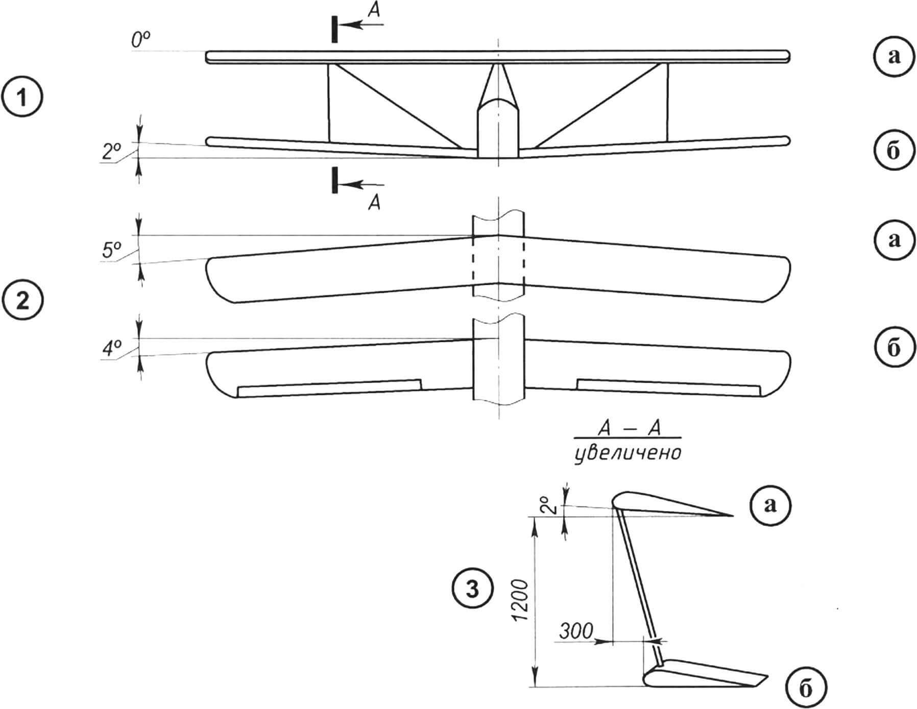
1 – transverse V; 2 — swept wings; 3 – installation angle
The installation angle of the upper wing is 2 degrees, the lower one is 0. The transverse V of the upper wing is 0, and that of the lower wing is 2 degrees. The sweep angle of the upper wing is 4 degrees, and that of the lower wing is 5 degrees.
The lower and upper consoles of each wing are connected to each other by struts made, like the struts, from duralumin pipes from the control rods of the An-2 aircraft.
1 — upper spar (pipe Ø18×1, 2 pcs.); 2 — lower side members (pipe Ø18×1, 2 pcs.); 3 — aircraft control stick support; 4 — spinal beam (2 pcs.); 5 — quadrangular frame (pipe Ø18, 3 pcs.); 6 — forming arc of the first and third frames (pipe Ø18×1, 2 pcs.); 7 – struts and braces (pipe Ø18×1, according to the drawing); 8 — lugs and lugs for fastening and hanging structural elements (as needed); 9 — trapezoid for fastening the rubber borehole shock absorber of the main landing gear (pipe Ø18×1); 10 — triangular frames of the tail section (pipe Ø18×1, 4 pcs.)
The fuselage frame is a truss, welded from thin-walled (1.2 mm) steel pipes with an outer diameter of 18 mm. Its basis is four spars: two upper and two lower. Along the sides, pairs of spars (one upper and one lower) are connected by an equal number and equally spaced posts and struts and form two symmetrical trusses. Pairs of upper and lower spars are connected by cross members and jibs, but their number and location at the top and bottom often do not coincide. Where the location of the crossbars and posts coincide, they form frames. Form-forming arcs are welded on top of the front rectangular frames. The remaining (rear) fuselage frames are triangular, isosceles.
1 — spar (steel pipe 30x30x2, 2 pcs.); 2 — spar extension (pipe Ø22, 2 pcs.); 3 — cross member (steel sheet s4); 4 — silent block (4 pcs.); 5 — eyelet for fastening the strut (steel sheet s4, 2 pcs.); 6 — hood support bracket (steel wire Ø8); 7 — strut (pipe Ø22, 2 pcs.)
The frame is covered with unbleached calico, which is then impregnated with homemade “enamelite” – celluloid dissolved in acetone. This coating has proven itself well among amateur aircraft designers. The front part of the fuselage (up to the cockpit) on the left side in flight is covered with panels of thin plastic. The panels are removable for easy ground access to controls in the cab and under the engine. The fuselage bottom is made of 1 mm thick duralumin sheet.
The tail of the aircraft is classic. All its elements are flat. The frames of the fin, stabilizer, rudders and elevators are welded from thin-walled steel pipes with a diameter of 16 mm. The linen covering is sewn to the frame parts, and the seams are additionally taped with strips of the same calico fabric impregnated with enamel. The stabilizer consists of two halves that are attached to the keel. To do this, an M10 pin is passed over the fuselage through the keel near the leading edge, and a tubular axle with a diameter of 14 mm is passed at the trailing edge. Ears with sector grooves are welded to the root rods of the stabilizer halves, which serve to install the horizontal tail at the required angle, depending on the mass of the pilot.
Each half is placed with an eye on a stud and secured with a nut, and the trailing edge tube is placed on the axle and pulled to the keel by a brace made of steel wire with a diameter of 4 mm.
From the editor . To prevent spontaneous rotation of the stabilizer in flight, it is advisable to make several holes for a pin instead of a sector groove in the ears.
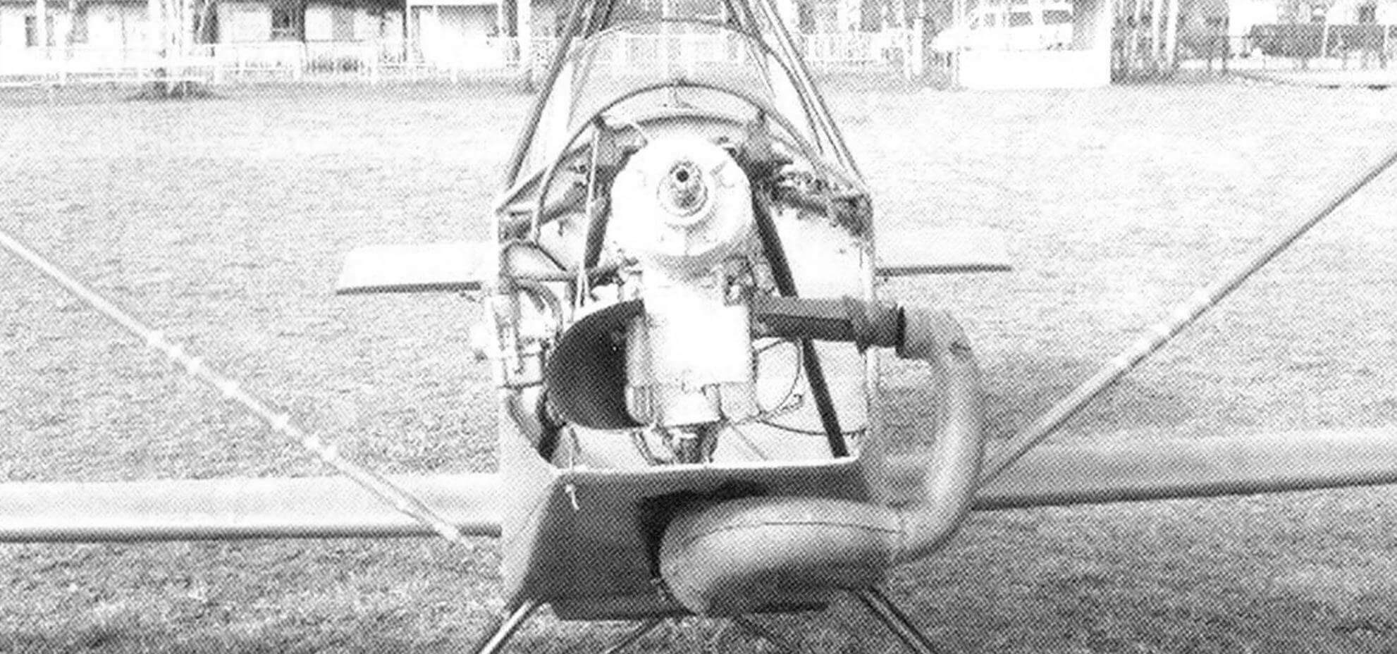
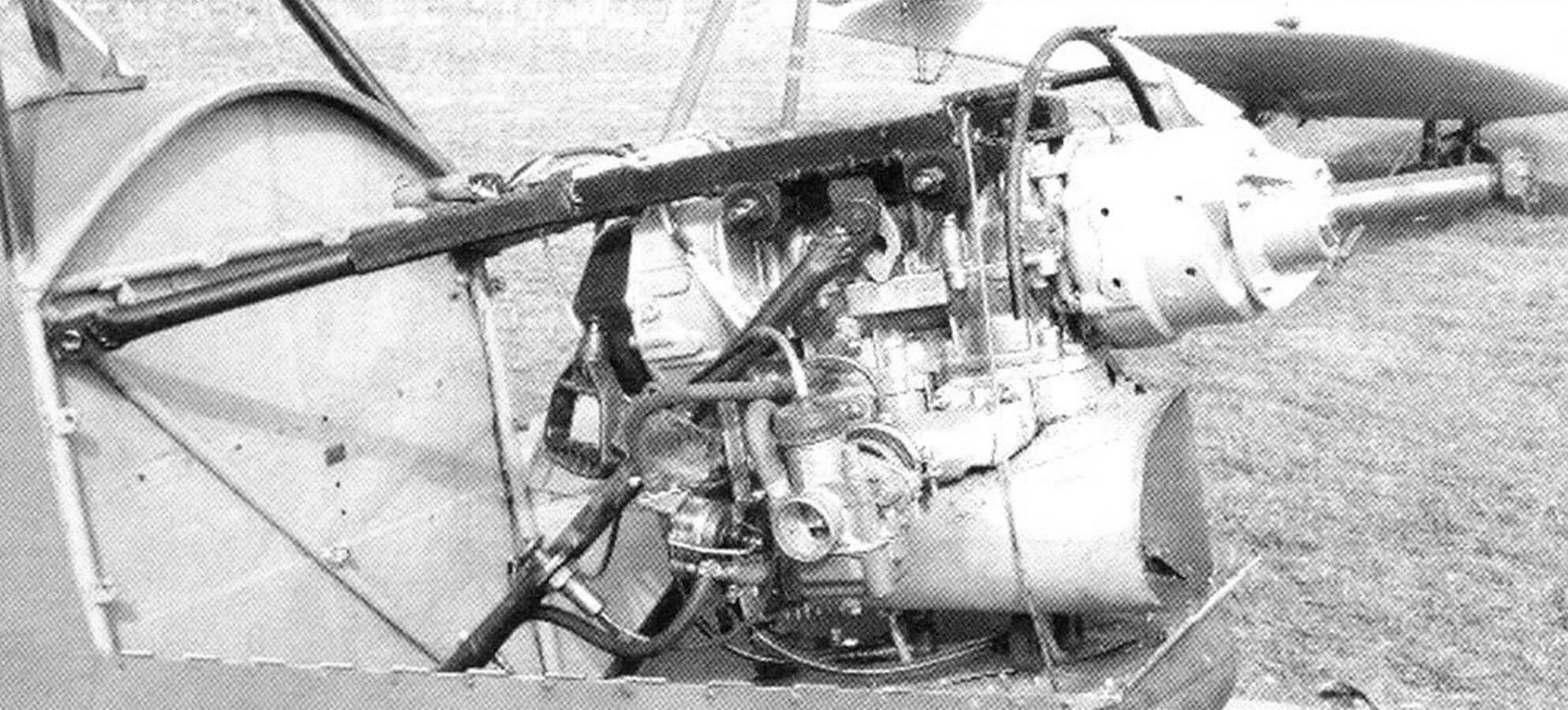
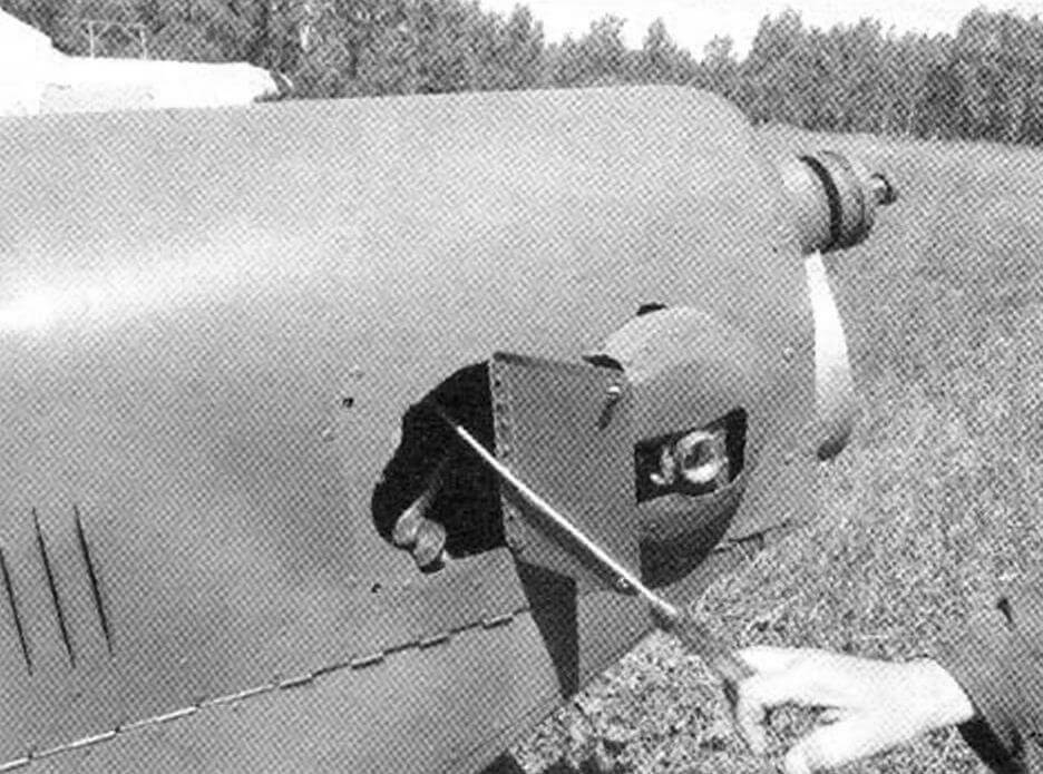
Now the plane is equipped with a propeller-driven installation with an engine from the Ufa Motor Plant UMZ 440-02 (the plant equips the Lynx snowmobiles with such engines) with a planetary gearbox and a two-blade propeller. Engine with a volume of 431 cm3 and a power of 40 hp. with a speed of up to 6000 per minute, air-cooled, two-cylinder, two-stroke, with separate lubrication, runs on gasoline, starting with AI-76. Carburetor – K68R. The air cooling system, although homemade, is effective. It is made in the same way as the Walter-Minor aircraft engines: with an air intake in the shape of a truncated cone and deflectors on the cylinders.
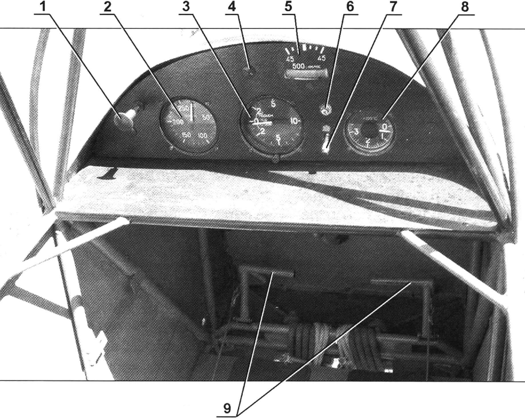
1 — carburetor throttle control handle; 2 — horizontal speed indicator; 3 — variometer; 4 — screw for fastening the instrument panel (3 pcs.); 5 — turn and slide indicator; 6 — engine failure warning lamp; 7 — ignition switch; 8 — cylinder head temperature sensor; 9 — rudder control pedals
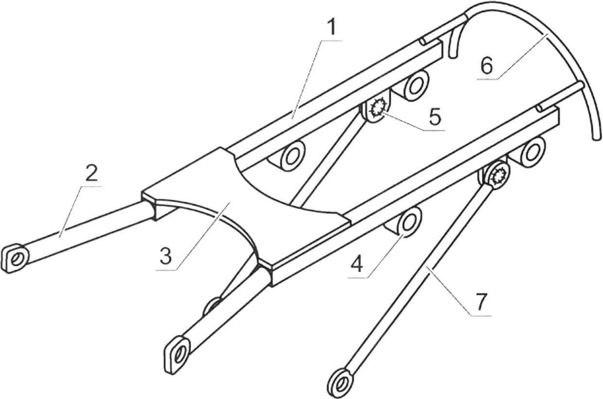
Previously, the plane had a modernized engine from the Whirlwind outboard motor with a power of only 30 hp. and V-belt transmission (gear ratio 2.5). But even with them the plane flew confidently. But the homemade two-bladed monoblock (from pine plywood) pulling propeller with a diameter of 1400 mm and a pitch of 800 mm has not yet been changed, although I plan to replace it with a more suitable one. A planetary gearbox with a gear ratio of 2.22… the new engine came from some foreign car. The engine muffler is made from a ten-liter foam fire extinguisher cylinder. The fuel tank with a capacity of 17 liters is from the tank of an old washing machine – it is made of stainless steel. Installed behind the dashboard. The hood is made of thin sheet duralumin. It has grilles on the sides for the outlet of heated air and on the right there is also a hatch with a cover for exiting the cord with a handle – they start the engine.
The propeller-engine installation is suspended on a simple motor mount in the form of two consoles with struts, the rear ends of which are fixed to the struts of the front frame-frame of the fuselage frame.
The aircraft’s electrical equipment is 12-volt.
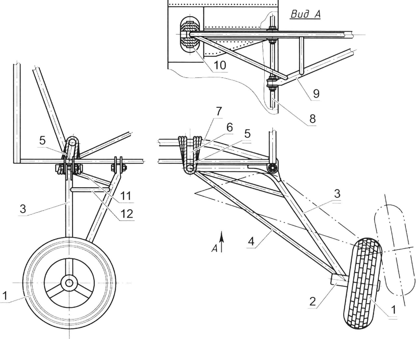
1 — wheel (Ø360, from a mini mokik); 2 — wheel hub; 3 — main stand (steel pipe Ø30); 4 — main strut (steel pipe Ø22); 5 — shock absorber (rubber band Ø12); 6 — travel limiter of the main rack (cable Ø3); 7 — shock absorber mounting trapezoid (fuselage truss element); 8 — fuselage truss; 9 — additional landing gear (steel pipe Ø22); 10 — shock absorber grip (pipe Ø22); 11 — additional strut (steel pipe Ø22); 12 — connection of racks (steel pipe Ø22)
The main landing gear legs are welded from sections of steel pipe with a diameter of 30 mm, and their struts are welded from pipes with a diameter of 22 mm. The shock absorber is a rubber cord wound around the front pipes of the struts and the trapezoid of the fuselage frame. The wheels of the main landing gear – non-braking, with a diameter of 360 mm – are from a mini-mokie, they have reinforced hubs.
The rear support has a spring-type shock absorber and a steerable wheel with a diameter of 80 mm (from an aircraft stepladder).
Control of the ailerons and elevator is rigid, from the aircraft control stick through rods made of duralumin tubes; The rudder and tail wheel are cable driven, from the pedals.
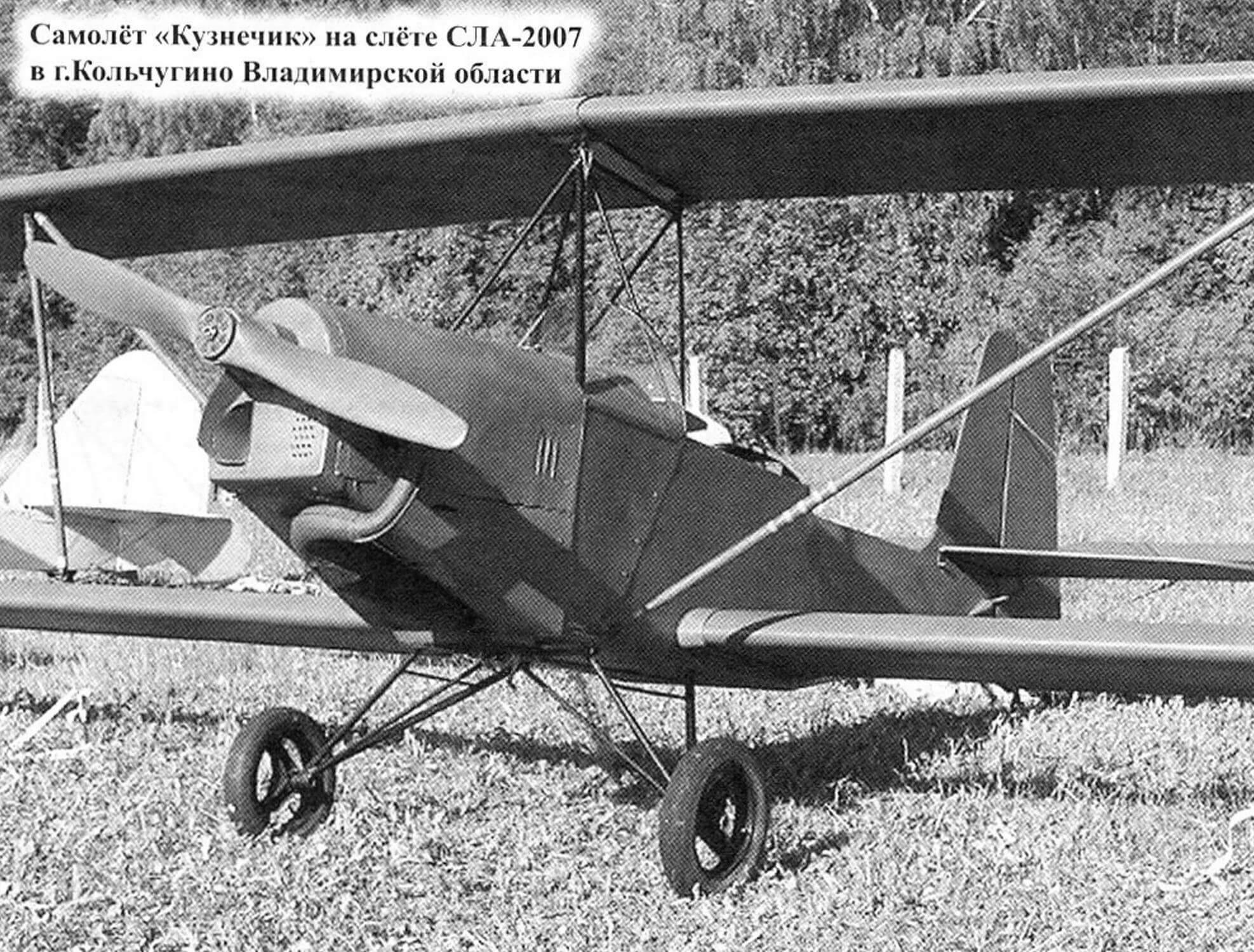
Construction of the aircraft was completed in 2004, and it was tested by pilot E.V. Yakovlev. The plane passed the technical commission. He made quite long flights in a circle near the airfield. A fuel supply of 17 liters is enough for about an hour and a half of flight, taking into account the aeronautical reserve.
Very useful advice and consultations during the construction of the aircraft were given to me by two Evgeniy: Sherstnev and Yakovlev, for which I am very grateful to them.
Flight performance
Empty weight, kg 110
Speed, km/h:
maximum 110
cruising 80—90
takeoff 50
landing 55
stall 45
Wing area, m 2 9
Engine power, hp 40
Fuel capacity, l 17
Flight duration, h 1.5
Operational overloads +3/-3
S. ZANYUKOV, Ivanovo
Recommend to read
 THE TRADITIONS
Ask the pilots of the postwar era, the Canon of the plane, they learned the alphabet flying up in the skies first with the instructor and then independently. "Yak-18", — unanimously... THE CEILING ON A WIRE…
The ceiling today has become a familiar element of the interior and in the office and in the home living room. Want to offer a simplified method of finishing the ceiling lining, which...
