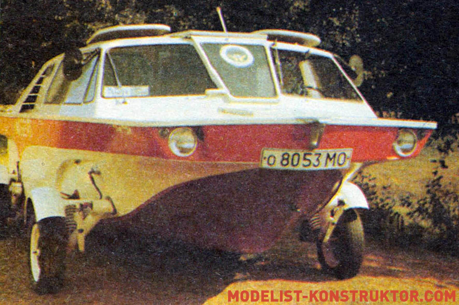
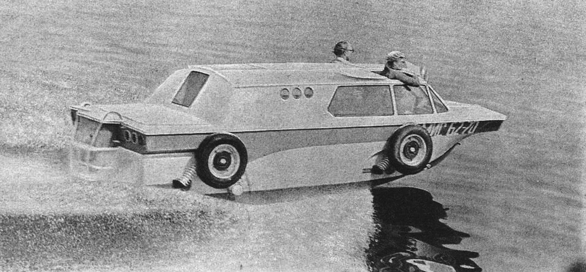
Curious glances accompany this crew everywhere. And it’s not surprising – it looks too unusual in the traffic… a boat on wheels. We are talking about a vehicle that exists so far in a single copy – the Triton planing amphibian. It was built by a man who, it would seem, is very far from technology. D.T. Kudryachkov is not a designer, but a professional musician who worked for a long time at the Moscow Academic Musical Theater named after K.S. Stanislavsky and V.I. Nemirovich-Danchenko.
Nevertheless, Dmitry Trofimovich showed the talent of an engineer and inventor, unusual for his profession, in order to solve a very difficult problem: making a full-size car not only float, but also plan (and, if desired, even transform it into a “clean” boat).
This is how original wheel suspensions with quick-release joints, an unusual steering gear and paradoxical “dry” brake hydraulic system connectors, never before seen in transport technology, appeared.
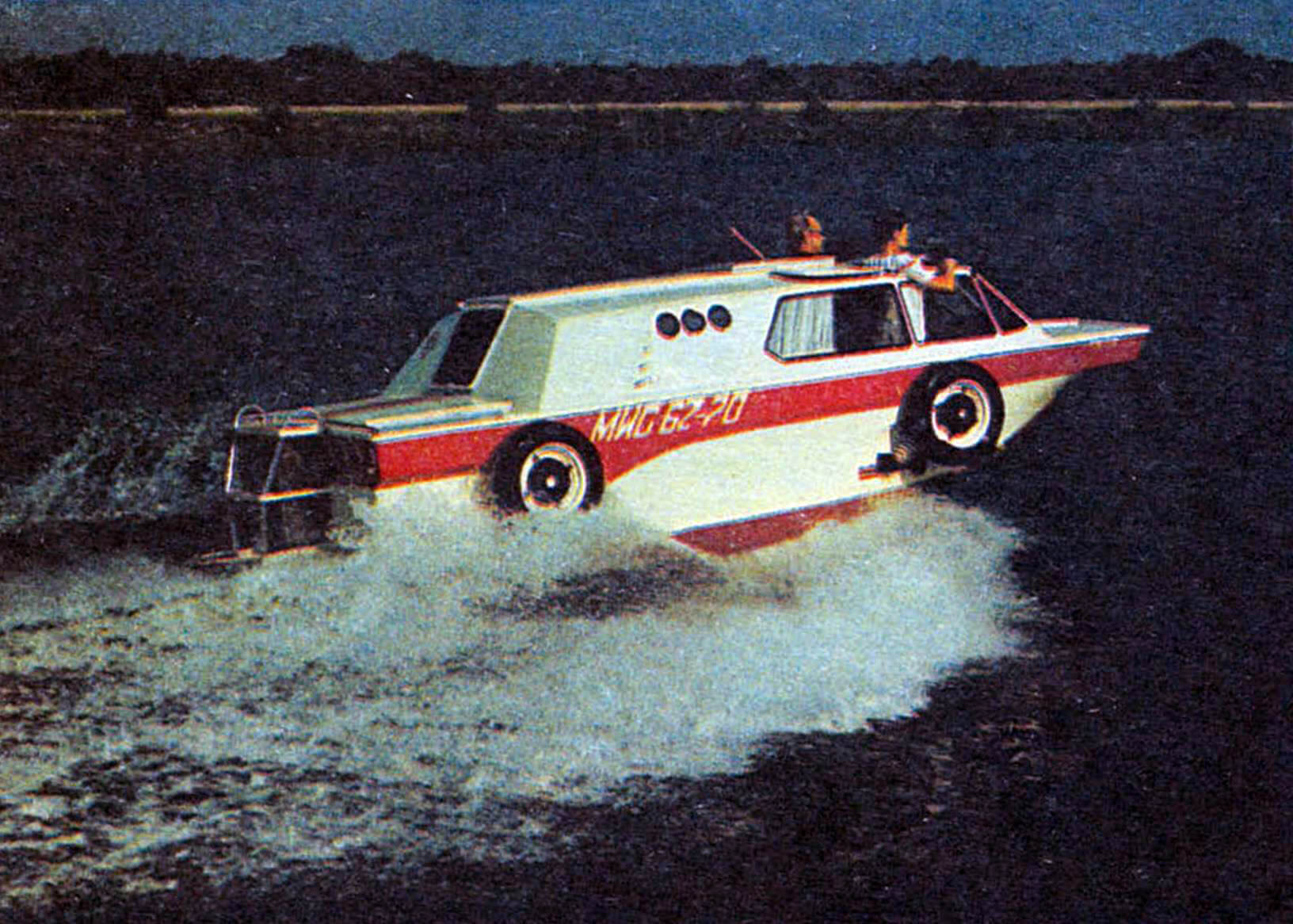
Sea trials confirmed the performance and reliability of all systems and components of the amphibian. The positive expert opinion of NAMI specialists served as the basis for registering Triton with the State Traffic Inspectorate. In turn, the State Inspectorate for Small Vessels (GIMS) allowed it to sail on all inland waterways of the “L” and “R” categories. Since then, the amphibian has been faithfully serving its owner for many years now.
Reports about Triton appeared in the electronic and print press. However, the current publication is the most complete. It reveals the logic of the search for original technical solutions that made it possible to create a vehicle that is equivalent in its performance properties both on land and on water. Along with a detailed description, extensive graphic material is presented, which will give interested readers and, possibly, followers not only an idea of the essence of the original design findings of D.T. Kudryachkov, but also, perhaps, an impetus to solve one’s own technical problems.
Surprise, as we know, is the beginning of all philosophy. For me, too, it all started with surprise, or, more accurately, with a question: will an amphibious vehicle really remain an inferior vehicle forever? For almost a hundred years, it has been accompanied by two “birthmarks”: low speed on the water and non-compliance with navigation safety requirements (low freeboard, poor maneuverability, zero seaworthiness). As a result, the water inspectorate prohibited its operation on a par with single-purpose vessels.
What’s the matter? What prevents a wheeled amphibian from being a speedboat on the water? It turned out to be a lot.
First of all, the familiar automotive design. It must be abandoned. Unlike a floating car, which on water has a speed of 7 – 9 km/h even with a factory body, the body of a real amphibian must meet the conditions of the new “habitat”, that is, uncompromisingly repeat the contours of the bottom of a high-speed boat.
The architecture of the surface part can be almost any, but again, taking into account the peculiarities of operation on the water. For example, a deck with a small slope, which is common in boat building, is desirable, since it is a workplace when locking, mooring to a pier or approaching an unequipped shore.
Further. Nothing should prevent the hull from planing. The entire automobile chassis – wheels, steering gear elements and transmission – must be completely removed from the water. There are no compromises here. Any fairings, screens or partial compression of the wheels will add speed of no more than 2-3 km/h, and the amphibian will still remain, albeit floating, but a car.
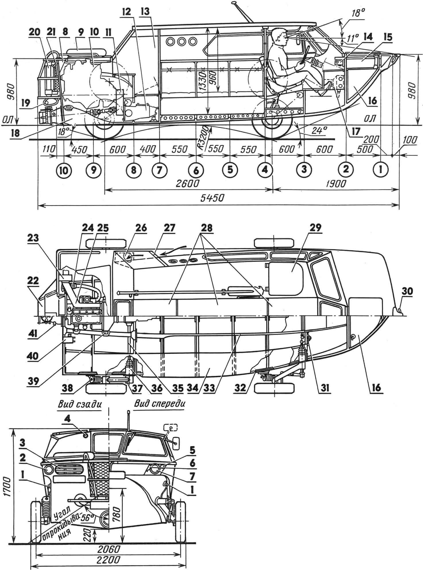
1 – dry hydraulic brake connectors, 2 – rear light, 3 – ventilation grille, 4 – hook light, 5 – turn signal light (also known as signal light), 6 – distinctive light, 7 – headlight, 8 – deck air duct, 9 – lifebuoy, 10 – engine, 11 – gearbox, 12 – gearbox, 13 – wardrobe, 14 – wheel suspension lift winch, 15 – trunk, 16 – fuel tank, 17 – cabin heater, 18 – water cannon, 19 – muffler, 20 — water cooling radiator, 21 — oil cooler, 22 — external ladder, 23 — exhaust manifold cooling fan, 24 — bellows, 25 — manifold casing, 26 — side air duct window, 27 — side air intake, 28 — folding roof panels, 29 — driver’s hatch, 30 — cleat eye, 31 — steering pendulum arm, 32 — local body reinforcement, 33, 34 — vertical and horizontal walls of the longitudinal stiffness side members, 35 — axle shaft, 36 — suspension support socket, 37 — lever axis suspension, 38 — suspension spring shoe, 39 — engine support, 40 — water-heat exchanger, 41 — water cooling system pipe (external circuit).
And one last thing. If for a car, even a significant excess of the recommended carrying capacity has little effect on its driving performance, then for an amphibian, the implementation of the planing mode requires strict coordination of its total weight with the engine power. There is a threshold that is unacceptable to cross: if the specific load on the engine is greater than the critical value, the amphibian ceases to be planing.
In our case, this threshold is 22 kg/hp, and due to the particularly difficult operating conditions of the engine on water, only 80% of its rated power is taken into account.
Preliminary estimates showed that, according to hydrodynamic requirements and habitability conditions, the overall dimensions of the Triton’s hull could not be less than the “minimum boat with a car engine” type, about 5 m long and 2 m wide, which has been established in boat building. It turned out that the weight of the equipped amphibian with the car filling will exceed the weight of a cabin boat of comparable size (1000 kg) by 300 kg. Thus, with a total displacement of 1300 kg, it was possible to use the GAZ-21 engine with a limitation of up to 80% of the rated power. The resulting specific load is 22 kg/hp. did not exceed the limits limiting the possibility of planing.
This explains the design features and layout of the Triton.
FRAME
Sharp chine hull lines with slight camber have a moderate deadrise (5% at the transom). The sides at the wheel suspension locations are vertical. The bow branches of the frames were given a very large camber, which made it possible to obtain a spacious deck, almost rectangular in plan. I note that in the theoretical drawing (and in the table of plaza ordinates) the zygomatic splash guards, vertical sections of the sides in the area of the suspensions and the loss of the bow frames are not shown for simplicity.
Structurally, the amphibian body is load-bearing. More precisely, a variation of it was used – a load-bearing bottom, the lower part of which is a solid box-shaped platform consisting of compartments-splits.
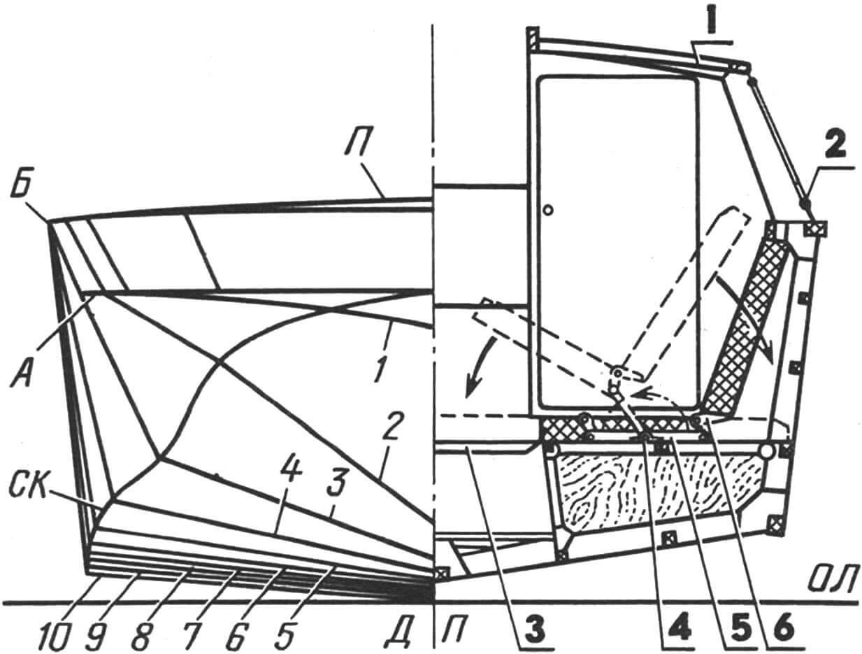
1 – cabin roof, 2 – rubber glass seal, 3 – removable flooring, 4-6 – lever seat layout device.
The strength structure of the hull is made according to a longitudinal-transverse pattern using oak and pine. The frames are assembled on brackets on both sides. Toptimbers have a variable section with widening towards the cheekbone. Longitudinal beams and sheathing sheets (aircraft plywood of various thicknesses) are joined at the edges. The outside of the body is covered with fiberglass. All connections are made with epoxy glue and crimped with screws or clamps. Only galvanized or cadmium-plated hardware was used. The internal surfaces of the case are coated with epoxy varnish. Its unsinkability is ensured by sealing the forepeak and sections of the load-bearing bottom.
The inclination of the transom is coordinated with the installation angle of the water jet and is equal to 6 degrees to the vertical. A rigid ladder is mounted on the transom: it is convenient on water and on land and at the same time serves as a guard for the radiators, muffler and reverse steering complex of the water jet.
The hull is made completely closed – without a cockpit and side hulls (narrow sections of the deck along the side). Instead, there is a through central passage along the axis of the amphibian. When the roof is open, it connects the bow and stern sections of the deck. To do this, the middle wing of the windshield is folded back, and the rear door and roof panels are folded into a compact package and attached to the right side.
TABLE OF PLAZA ORDINATES
| Line | No. of frames | |||||||||
| 1 | 2 | 3 | 4 | 5 | 6 | 7 | 8 | 9 | 10 | |
| Heights from the main one, mm | ||||||||||
| Keel | 700 | 210 | 110 | 80 | 60 | 46 | 33 | 24 | 10 | 0 |
| Skula – SK * | 740 | 610 | 360 | 250 | 185 | 144 | 125 | 110 | 90 | 74 |
| Board – B | 950 | 950 | 950 | 950 | 950 | 950 | 950 | 950 | 950 | 950 |
| Deck – P | ||||||||||
| in DP | 985 | 1000 | — | — | — | — | — | — | 995 | 980 |
| A | 770 | 770 | 770 | — | — | — | — | — | — | — |
| Half-latitudes, mm | ||||||||||
| Board – B | 850 | 900 | 930 | 950 | 950 | 950 | 950 | 950 | 950 | 950 |
| Skula – SK * | 250 | 520 | 650 | 770 | 830 | 845 | 845 | 845 | 845 | 845 |
| A | 740 | 810 | 883 | — | — | — | — | — | — | — |
| * The junction points of the side and bottom branches of the frames are given. | ||||||||||
Since a lot of components and assemblies “unnecessary” for an ordinary boat had to be hung on the hull, the problem of weight reduction became especially acute. At all stages of the work, both the choice of materials used and the dimensions and cross-sections of parts were carefully justified.
An important reserve for weight reduction was the multi-purpose use of structural elements, subject to their rational arrangement. For example, the vertical spars of the load-bearing bottom also serve as the walls of the lockers; they, being reinforced in the aft part, form the basis of the sub-engine foundation. The different sizes of spacing (400, 550, 600 mm) are not only strictly linked to the layout of the internal space, but also eliminate duplication of the transverse set, since they are consistent with the installation dimensions of the chassis units. The support units of the wheel suspensions are reinforced by two pairs of reinforced frames, and two pillars on the sides of the central aisle partially relieve the load on the roof’s load-bearing structure and at the same time serve as a support for the mast of additional sailing equipment.
CABIN
Refusal of the on-board floodplains made it possible to expand the cabin from side to side, which significantly increased its useful volume. The interior space is conventionally divided into two parts: a running tube, the border of which is the backs of the front seats and pillars, and the salon with a galley and a wardrobe located aft of it.
The front seats – the driver’s and navigator’s seats – have a non-removable aluminum frame and can be installed in two levels with a height difference of 400 mm. The lower position is normal – “car”; The upper one is used only on the water to improve visibility in difficult sailing conditions. For this purpose, hatches are made above the seats. Their covers fold back, and the sun visors, turned upward, protect the driver’s face from the oncoming air flow, which is very significant at a speed of 40-50 km/h.
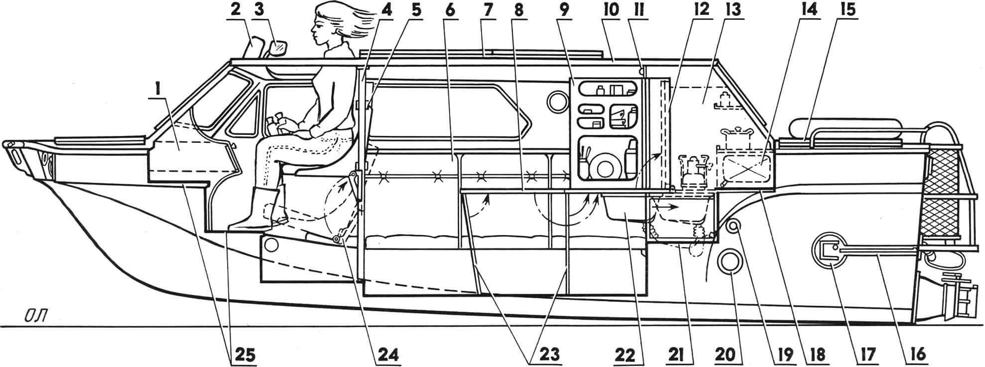
1 — navigation box for small items, 2 — sun visor in the wind deflector position, 3 — rearview mirror in the “afloat” position, 4 — pillars, 5 — seat back slider, 6 — passenger seat, 7 — roof panels folded , 8 — folding table, 9 — galley door, 10 — roof spar, 11 — lampshade, 12 — table in folded position, 13 — galley, 14 — drinking water tank, 15 — engine compartment roof, 16 — suspension shoe guide, 17 – shoe trap, 18,21 – steps of the rear internal ladder, 19 – dry hydraulic brake connector, 20 – suspension support socket, 22 – retractable sink, 23 – table legs, 24 – seat lifting mechanism, 25 – steps of the front internal ladder.
Six seats in the cabin are located along the sides on lockers; four of them are equipped with hinges and can easily be transformed into a full-size double bed across the hull. To reduce weight, all seats are made of 50 mm thick PVC-1 foam boards, covered with foam rubber and covered with leatherette.
Equipment and food supplies are stored in twelve lockers and a large trunk in the forepeak (above the gas tank). In addition, there are side pockets and a navigator’s “bag” for route maps, binoculars, film and camera equipment and small items.
The interior ventilation is natural – through hatches, doors and roof panels above the central passage that are slightly open or completely open in any combination.
A few words about the galley. Essentially, it’s as if there isn’t one in the cabin, since when the table is pushed into a niche, it is closed and looks like a wardrobe located opposite. However, there is enough space for two “Bumblebees”, a pull-out sink with a tap from a drinking water tank and all kinds of kitchen utensils. The niches of the volumetric door store a thermos, small dishes, spices, tea, coffee, and sugar.
POWER POINT
The GAZ-21 engine, gearbox with differential from Zaporozhets and a homemade gearbox form a single power unit. It is mounted on five rubber cushions close to the transom, above the water jet. With this arrangement, the length of the engine compartment is extremely reduced.
Access to the crankshaft ratchet is through a hole in the transom, covered by a spring-loaded cover with a seal.
The engine cooling system is dual-circuit. Its aft location required a number of additions: a guide casing was installed for more intense airflow of the water radiator; the standard four-blade fan impeller has been replaced with a lightweight six-blade one, turned in the opposite direction; An oil cooler from GAZ-51 was additionally installed. The air enters them through a separate deck air duct and partly through the wide gap between the transom and the fan shroud.
When the water jet is operating afloat, a second external cooling circuit is automatically connected, consisting of a water heat exchanger embedded in the line between the radiator and the water pump. Sea water also enters the oil cooling coil in the engine crankcase and into the gearbox jacket.
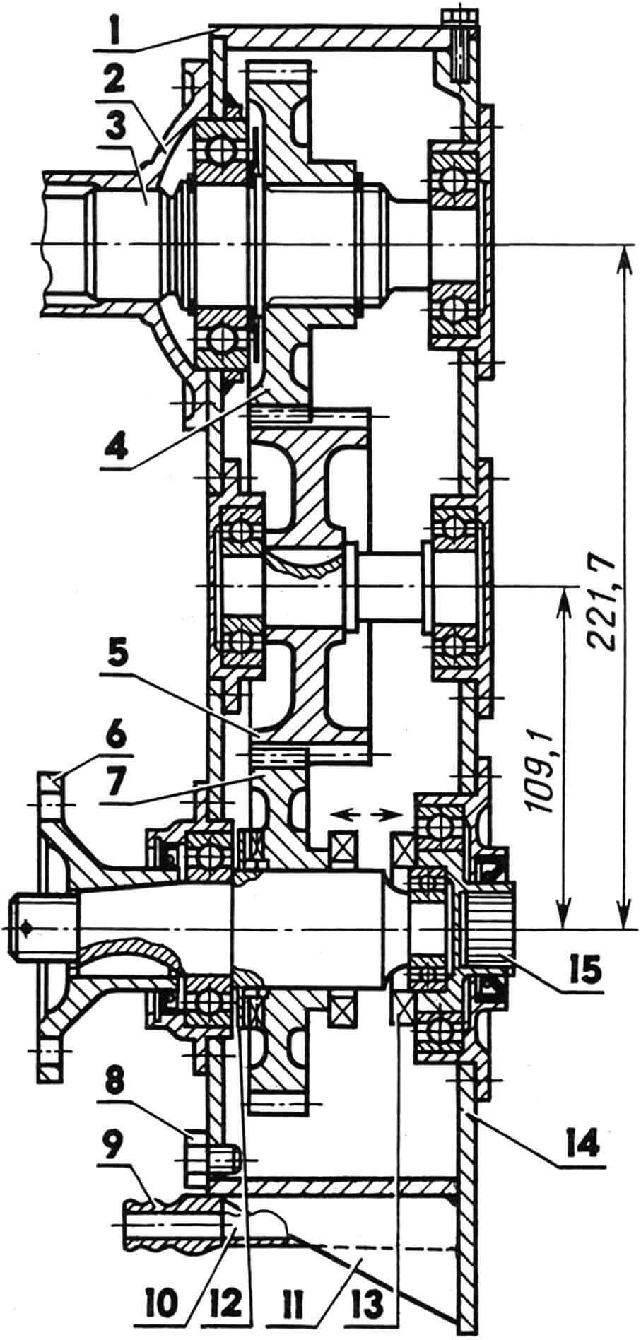
1 — gearbox cover, 2 — GAZ-21 gearbox cover, 3 — input shaft, 4 — drive gear, 5 — intermediate gear, 6 — water jet drive flange, 7 — driven gear with cam clutch, 8 — drain plug, 9 — water cooling jacket fitting, 10 – water cooling jacket, 11 – stiffener, 12 – driven shaft cams, 13 – gearbox drive shaft cams, 14 – gearbox housing, 15 – gearbox drive shaft.
The exhaust gas manifold, enclosed in a lightweight casing, is cooled on land and on water by a two-speed centrifugal electric fan, the control of which is interlocked with the gas pedal. When the engine warms up, the fan is turned off. At medium speeds it turns on at low speed and at high speeds (over 2500 rpm) at high speed.
Exhaust gases are discharged out through a pipe that has a compensation spacer in front of the transom – a bellows that absorbs engine vibration. Behind the transom is a muffler, rigidly fixed under the bottom step of the ladder.
Air enters the engine compartment through air intakes located on both sides of the cabin. It is directed through box-shaped pipes to the engine and gearbox and then discharged through special grilles in the transom.
A gear reducer is used to transmit power to the water jet and gearbox. Its gear ratio is 19:18. Spur gears with a module of 3 mm and heat treatment up to 48-52 HRC. The noise from such gears, compared to helical gears, is greater (8-10 dB), but their use has made it possible to reduce the dimensions and weight of the gearbox. (The gears were later replaced with helical gears, although it was not easy to squeeze them into the old housing.)
The gearbox housing is welded. All holes and seats were machined on a boring machine. A water cooling jacket is welded onto the side walls and bottom of the gearbox.
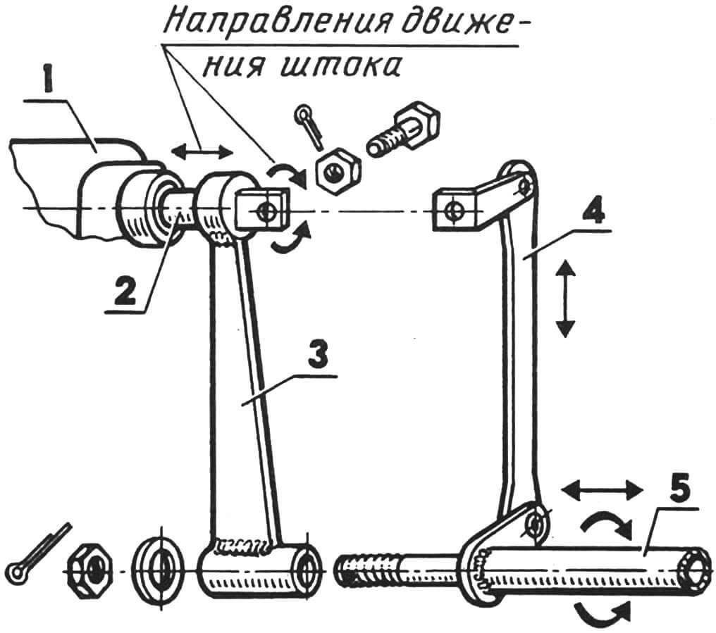
1 – rear cover of the gearbox, 2 – slider rod, 3 – console transmitting reciprocating motion, 4 – rod transmitting rotational motion, 5 – gearbox control shaft.
The gearbox control is located in the “water jet – neutral – wheels” sector, located to the right of the driver, next to the gear shift lever. Here is the water cannon reverse handle.
A “pantograph” was introduced into the gearbox control line – a kind of intermediate unit, necessary because the control shaft passing under the slides and the box slider rod are at different heights.
WATER CAR
The Triton’s water-jet propulsion system is made of stainless steel. The design described in the magazine “Boats and Yachts” No. 11 and 25 was adopted as the basis. Of course, with significant changes: the inlet of the water conduit was expanded; an inspection hatch is installed; the fairing of the straightening apparatus is extended; in the removable (threaded) part of the fairing there are bearings and oil seals for the rear shaft support; the cross-sections of the rotor blades and straightening apparatus have been halved; the gap between the shell and the rotor blades is maintained at 0.4 mm; The reverse steering system has been significantly simplified.
The water conduit is welded from two symmetrical halves, the knockout of which was greatly facilitated thanks to preliminary longitudinal cuts on the future cylindrical part of the blanks. The halves, fitted end to end and tied together on a block with wire bands, were welded in one pass. This technology, in my opinion, gives the least distortion of the geometry of the water pipeline and extremely reduces the length of the welds.
CHASSIS
Since none of the factory wheel suspensions were suitable for the Triton, we had to independently manufacture independent single-lever suspensions of a welded design with the installation angles of the king pin, camber of the front wheels and toe angle of the rear wheels included in them during manufacture. The toe-in angle of the front wheels is adjusted by a transverse rod inside the body.
The axes of the levers of all pendants are hollow, with a large inner diameter. They are made with such so that the side rods of steering are freely moved in the front, and cardan hinges, stars and bearings with eccentric buildings that regulate the tension of the chains are placed in the rear.
1-seal, 2-rubber protective cover, 3-“Bayonet” protrusion on the axis of the suspension lever, 4-“Bayonet” protrusion on the hull of the nest-powders, 5-oils, 6-amphibian housing, 7-hull, 8 hull, 8 – The axis of the pendant lever, 9 – side steering rod, 10 – ball hinges, 11 – nylon sleeve, 12 – lever of the suspension, 13 – rocker, 14 – support of the rocker.
When installing the axis of the levers of pendants on the amphibian, they are inserted into the nests with caps with nylon bushings pressed in them and turn into working position. These nodes are rapidly detachable articulated joints resembling a byonet. But if, with a conventional bayonet connection, the parts are motionlessly fixed relative to each other, then the axis of the levers of the “Tyton” have radial freedom in an unequal sector up to 1,70 degrees, which is enough for the oscillatory cycle of their work and to raise the wheels from water to heights to a height Above the waterline.
The springs and hydraulic shock absorbers are selected the same suspensions for both pairs-from the ZAZ-968 car. The upper supports of the springs and shock absorbers are special traps, into which they are pushed along the guides and snap in the pins of the shoes of the springs.
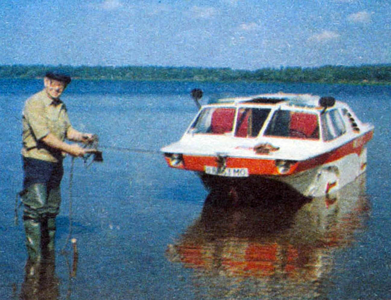
On the water, pendants with wheels rise along the sides of a cable winch. Thus, Triton, unlike other amphibians, can be afloat for an unlimited time, since all the units of the chassis are not corroded and do not grow algae and at any time are ready for use on land.
STEERING
Made on the basis of the corresponding mechanism of the “Cossack”. True, with significant additions due to the use of a fundamentally different steering wheel drive scheme, the essence of which is to combine the longitudinal axis of the side rods with the axis of swinging levers of pendants and in the transmission of efforts “to rotary fists through the rockers that have support on the levers of suspensions. In this form, each suspension with a spring, a shock absorber and elements of the steering drive is a single mounting unit that does not require any adjustment when installed on the case.
The kinematics of this scheme, unlike all other circuits of a car steering wheel drive, allows you to raise them unhindered and without violation of the installation angles of the wheels to an unusual height – 700 mm.
1-Cloup of Control of Control to Wheels or Vodomet, 2-steering wheel drive, 3-intermediate traction, 4-rocking, 5-horizontal traction, 6-pendulum lever, 7-Ampyl nest, 9-lever axis Suspensions, 10 – lateral traction, 11 – ball hinge, 12 – rocker, 13 – lever of the suspension.
The shaft of the steering mechanism has a device with a cam clutch that includes a waterboard sash, or wheels control mechanism in the operation or drum of a cable drive.
All communications of the engine control, the gearbox, the gearbox, the reversal of the water interference, as well as the parking brake and the speedometer, pass under the slopes of the passenger compartment.
TRANSMISSION
Half -axles with cardans connected to the axes of the leading chain gear stars are going on to the sides in the area of the supports of the gearbox. The bushings (two of them per wheel) work inside the hermetic tubular levers of the rear pendants in an oil bath. Their tension is regulated by the rotation of the eccentric body of the bearings.
1, 5-nylon bushings, 2-cardan hinges of the half-axis, 3-nesting ropa of the rear lever of the suspension, 4-lead shaft, 6-body of the axis of the suspension lever, 7-amphibian housing, 8-spray compaction, 9, 13-eccentric Bearing housings, 10-11 mounting window cover, 11-a checkpoint of eccentric buildings, 12-leading stars, 14-cover of the leading node, 15, 16-windows of drive circuits, 17-slit for a check-fixer, 18-holes for lubricating the bearing , 19-the size of the eccentricity of the axes of the nest-powder and the leading shaft, 20-one of the two pipes of the suspension lever, 21-spacer, 22-driven shaft (wheel axis), 23-24-wheel hub, 25-driven Stars, 26 – Stop puck, 27 – Crown nut to eliminate the backlash of bearings, 28 – the lid of the driven unit.
The favorable distribution of the mass of “Triton” to the wheels is reached thanks to the inclination of the front and rear pendants back. This also gives a smooth move, because on the irregularities of the road, the suspensions experience less dynamic loads. BRAKE SYSTEM
Here, too, the “Cossack” brake system was used in full: the foot hydraulic drive is separate – on the front and rear wheels, and the manual cable (parking) – only on the rear.
To simplify the installation or dismantling of suspensions in the hydraulic system, I used another high -speed connection – a “dry” hydraulic machine connector, which allows you to connect or disconnect the brake hoses of the wheel without loss of brake fluid and without subsequent labor consumption of the entire system.
There are four such connectors on Tyton. Each of them consists of two hemispheres, covered with elastic membranes: on -board (it ends the interior pipeline) and the return (consumable) fixed at the end of the wheel pipe. The response is packed by the pitch nuts to the on -board.
1 – Board of the case, 2 – a nut of the on -board hemisphere, 3 – the pipeline of the main brake cylinder, 4 – on -board hemisphere, 5 – membranes (2 × 6 pcs), 6 – clamping washers, 7 – retaliatory (consumption) hemisphere, 8 – 8 – The hose of the wheeled section of the hydraulic system, 9 – membranes, 10 – the pitch nut, 11 – valves of primary pumping of the hydraulic system.
When pressed on the brake pedal, both membranes are deformed, squeezing the liquid from the consumable hemisphere into the wheel cylinder of the wheel – inhibition occurs.
The volume of the flow rate of the hemisphere is 3.5 times larger than the volume used in the workers of the hydraulic cylinders, therefore, any operational losses will be compensated. In the absence of brake fluid in any hemisphere (or even in all four), the brake system does not refuse: when pressed on the pedal under the action of pressure in the highway, the membranes break through through, and the brake fluid, freely flowing from the internal highway, performs its work as In the usual hydraulic system of the car.
ELECTRICAL EQUIPMENT
It is completely automobile, although the light alarm is made according to two schemes with the Earth – Water switch. The headlights are also left in the “Water” scheme in order to use them when approaching the shore in the dark. The front rotation indicators work as light lights. Both schemes are equipped with “masses” circuit breakers.
The headlights, frivolous lights and distinctive lights are “drowned” in niches along the edges of deck spins and are well protected by overhanging sections of the nasal deck.
The standard indicators of the engine operating mode are supplemented by an electronic tachometer and a “water -spideometer”, which used a manometer with a scale overlap with kilometers. It is possible to control the temperature of the oil in the engine. To do this, the TM-101 sensor installed in the oil submarine, from time to time, is connected by a two-position toggle switch on the dashboard to the water temperature indicator.
Technical data of Amphibia “Triton”
Dimensions: length, mm 5450
Width, mm 2200
height, mm 1700
Base/track, mm 2600/2060
Road clearance, mm 220
Turning radius, mm 7000
Complete mass (displacement), kg 1300
Distribution of mass on the axis, % 50/50
Engine power: nominal, l. With 75
Permissible on the water, l. With 60
Maximum speed: on the highway, km/h 90-110
on water, km/h 36-50
Vodomet: single -stage, rotor diameter, mm 219
Rotor step, mm 215
Fuel consumption: on the highway, l/100 km 12
in the glingation mode, l/100 km 18
The capacity of the cabin in the guest version, people 8
The number of places when moving 4
The “gas” manual control buttons and a carburetor air defense buttons are also displayed on the shield.
Thanks to the listed “complications” with which amphibians are equipped (rapidly supporting compounds, etc.), it is extremely simply turned into a “clean” boat. Having removed the suspensions, for example, you can tow water -skiers or take on board two more passengers or an additional supply of fuel, products, equipment, since without suspensions the carrying capacity (displacement) of amphibians increases by 170 kg.
To do this, it is enough to unscrew the four pitch nuts of the “dry” connectors, disconnect the side traction from the pendulum levers and put out the outer ends of the manual brake cables. We carry out such a simple operation almost every time for a month and a half we leave for the Moscow Sea in the summer.
D. Kudryachkov
Recommend to read
 TRY TO CUT
Dried to saw off the branch isn't too difficult if the tree is not very high. But otherwise, the task is not only difficult, but dangerous as well. There is, however, a way that makes... OVEN-STOVE
These small, simple oven have a different design and used for different purposes. Entirely metal and heating, are made of sheet steel of different thickness. They are divided into simple...
