
Biogas. Used as far back as ancient China and then “rediscovered” millennia later as a “non-conventional, environmentally clean energy source of the 21st century,” it is attracting growing attention in our country too. Evidence of this is, in particular, the steady rise in publications related to biogas—including in the pages of Modelist-Konstruktor (see, for example, No. 1’87, 5’88). This article too confirms both the steady growth in popularity and the inexhaustibility of the topic of technical solutions for producing and practically using the “valuable gaseous product of anaerobic (i.e., occurring without access to air) fermentation of organic matter that was formerly classed as worthless waste.”
Biogas is essentially a “hellish” mixture. Its main components are methane (55–70%) and carbon dioxide (28–43%); other compounds are present in small amounts, including chemically aggressive ones—e.g. hydrogen sulfide. This must be taken into account when building a biogas plant, bearing in mind that on average 1 kg of organic matter that is 70% biologically degradable yields 0.18 kg methane, 0.32 kg carbon dioxide, 0.2 kg water, and 0.3 kg of undecomposed residue.
Since the decomposition of organic waste with release of biogas is the result of activity of certain types of bacteria, the environment has a major effect—in particular, temperature. The warmer it is, the higher the rate and degree of fermentation of the organic feedstock.
And since, as they say, we are not in Tashkent, the fermenting mass needs to be heated. The simplest way to do this is apparently to use the heat given off when manure decomposes. That is where the “gas-producing center” of the plant—the so-called “methane tank” (digester)—should be placed. It can be made from 2–5 mm stainless steel sheet, welded twice: first by electric welding, then (for reliability) by gas welding. Provision must also be made for refilling the biogas plant with feedstock and for removing waste from the working zone.
One successful technical solution led to another, and the design eventually took the form shown in the illustrations.
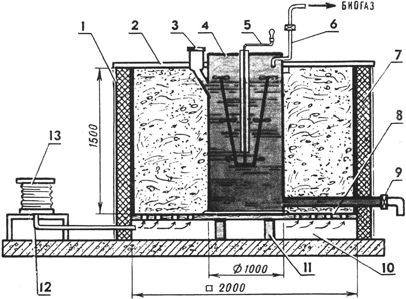
1 — aerobic fermenter (corrosion-resistant—e.g. wooden—box structure with hinged rear and front walls), 2 — cover (wooden panels), 3 — digester fill neck (welded from 2.5 mm stainless steel), 4 — digester (suitable-size tank for chemical fertilizers, petroleum products; or welded from 2.5–5 mm stainless steel), 5 — mechanical stirrer (welded from stainless steel), 6 — biogas outlet pipe, 7 — thermal insulation layer of expanded clay or foam plastic, 8 — slatted floor (100×100 mm wooden beams), 9 — drain valve, 10 — service channel, 11 — brick stand, 12 — welded guide bushing (100 mm length of 32×5 pipe, stainless), 13 — blower (or forge bellows).
The cylindrical metal tank—the digester—with fill neck, drain valve, mechanical stirrer, and biogas outlet pipe is combined into a compact unit (see fig.). For building it, tanks from chemical fertilizers and other parts and assemblies in stainless steel are very suitable. The “gas-producing center” itself is located inside the aerobic fermenter, which can be rectangular (e.g. made from lumber).
The fermenter has two removable side walls for easier unloading of spent manure. The floor is slatted. Air is driven through a service channel beneath it using a blower such as forge bellows or a dedicated air blower.
The fermenter should be covered on top with wooden panels. To reduce heat loss, the walls and bottom are made with a thermal insulation layer.
Prepared manure with cow urine is poured into the digester through the neck. The moisture content of the “feedstock” should be 88–92%, with the level of this slurry monitored at the lower part of the fill neck. The aerobic fermenter is filled through the top opening with solid bedding manure or a mixture of the latter with loose dry organic filler (straw, sawdust) at 65–69% moisture.
When air is supplied by the blower, organic matter in the fermenter begins to decompose and heat is released. This is enough to heat the digester, whose contents are mixed (by the stirrer and by convection). As a result, biogas is produced. It collects in the upper part of the digester. Through a dedicated pipe, the biogas is led to the “main” and used for domestic purposes.
When operating this biogas plant (as with most similar devices), remember the need to maintain biochemical balance. Sometimes the rate at which acids are produced by bacteria involved in anaerobic fermentation is higher than the rate at which they are consumed by another group of bacteria. In that case, as the magazine has noted in earlier articles, the acidity of the mass rises and biogas output falls. The situation can be corrected by reducing the daily portion of feedstock, by increasing its solubility (e.g. with hot water), or by adding a neutralizing agent (e.g. lime milk, washing soda, or baking soda).
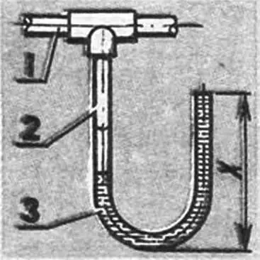
1 — biogas pipeline, 2 — V-shaped tube (length of free leg “X” must exceed the biogas pressure in the main expressed in mm of water column), 3 — condensate.
Biogas production can drop if the carbon-to-nitrogen ratio is upset. This is corrected by adding nitrogen-containing material to the digester—urine or small amounts of ammonium salts commonly used as chemical fertilizers (50–100 g per cubic meter of feedstock).
Do not forget that high humidity and the presence of hydrogen sulfide (which can reach 0.5% in biogas) promote increased corrosion of metal parts. The condition of all other elements of the fermenter and digester should be checked regularly, and any damage should be carefully protected (ideally with red lead in one or two coats, then two coats of any oil-based paint).
The waste after processing in the biogas plant is sanitized and makes excellent fertilizer. But besides that, the main product—gas—is produced, in a volume quite sufficient for a two-burner stove.
Such a plant pays for itself in about a year just from waste utilization on a smallholding.
Modelist-Konstruktor No. 4’96, A. KOVALEV
Recommend to read
 IN SEARCH OF PROFILE
The rocket plane with Delta wing design is widely known, repeated in dozens of models. However, leading athletes of the country are constantly experimenting, looking for even the... A SNOWMOBILE FOR EVERYONE
The propulsion system of this snowmobile consists of a rubber-fabric track made from a 300 mm wide conveyor belt and joined into a ring using a hinged loop. On its outer surface, cleats...
