“The school automatic weather station, constructed by students of secondary school No. 5 in the city of Klin, is of technical interest. The precipitation sensor and its registration on the control panel are originally conceived and implemented. The wind direction and speed indicators, as well as the thermometer, are interesting.
Such weather stations can also find application in the national economy — when setting up agrometeorological stations in collective farms and state farms.”
(From the conclusion of the head of the weather station in Klin)
The correspondence exhibition “Create, Invent, Try” continues. The first results have been summed up by the exhibition council, which operates at the editorial office of “Pionerskaya Pravda”. Among the works awarded prizes are those whose stories in the newspaper pages caused the most enthusiastic response from readers. “Send drawings, write in detail how to replicate the design,” — such letters come to the correspondence exhibition council after most publications. Many want to make the same laryngophone classroom in their school as in school No. 16 in Zhigulevsk, or a device for detecting faults in hidden electrical wiring (work by E. Ponomarev from school No. 4 in Saransk). The automatic cherry pit remover (author V. Volkov from Tula school No. 1) caused a stream of questions: everyone needs such an automaton in summer. Specialists paid attention to the work of O. Grankin from the Gorky school in Taldy-Kurgan (Kazakh SSR) — a miniature drill powered by pocket flashlight batteries.
The school hydrometeorological station, which is described in this issue, also appealed very much to the pioneers. After all, having your own weather station at school, and an automatic one at that, is so tempting. But the device constructed by the Klin boys can be used not only in school. The main advantage of their hydrometeorological station, which was noted by the exhibition council, is its suitability for the national economy. Such a station will serve well in collective farms and state farms, at taiga drilling sites and in fishing villages.
The names of the first prize winners of the All-Union Correspondence Exhibition “Create, Invent, Try” are now known. Awards — valuable prizes and certificates — were received by the creators of the most useful and original designs. But there is still much time until the exhibition closes: its final results will be summed up in May 1972. So young designers who have recently completed work on a device, model, or automaton will still have time to present them to the exhibition council. Our magazine will try to publish descriptions of the most interesting findings.
We are waiting for your letters, friends!
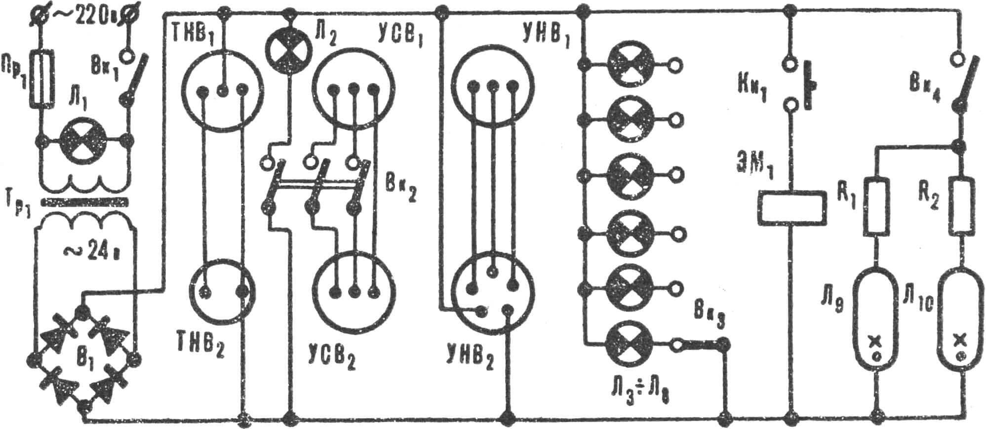
Pr — fuse, Vk1 — control panel “power” switch, Vk2 — three-pole wind speed indicator switch, Vk3 — panel lighting lamp switch, Tr — step-down transformer 220/24, V — rectifier, L1 — “panel on” signal lamp, L2 — “wind speed indicator on” signal lamp, L3—L8 — rain gauge signal lamps, L9 and L10 — fluorescent lamps, Kn — “drain water” button, EM — rain gauge electromagnet, R1 and R2 — ballast resistances (23 Ω), TNB1 — outdoor air thermometer recording device, TNB2 — thermometer sensor, USV1 — wind speed indicator, USV2 — generator-sensor, UNV1 — wind direction indicator, UNV2 — sensor.
Three years ago we conceived building a school automatic hydrometeorological station (Fig. 1). Four seventh-graders took on the work: Nikolai Ponomarev, Alexander Zasosov, Sergei Korolkov and Vyacheslav Propoy. They created one version, then a second, more perfect one — this reconstruction was carried out in 1970/71, when the boys were finishing ninth grade.
The main feature of our station is remote measurement. Without leaving the school building, you can find out the direction and speed of the wind, the outdoor air temperature, and the amount of precipitation. In addition, we measure atmospheric pressure, humidity and indoor air temperature.

1 — impeller, 2 — roof, 3 — rain gauge contact housing, 4 — large rain gauge reservoir, 5 — float, 6 — small rain gauge reservoir, 7 — drain tube, 8 — valve, 9 — electromagnet, 10 — plug connector, 11 — wind direction indicator sensor, 12 — thermometer sensor, 13, 16 — ball bearings, 14 — frame, 15 — current collectors, 16 — seal, 18 — rod, 19 — weather vane, 20 — wind speed indicator sensor.
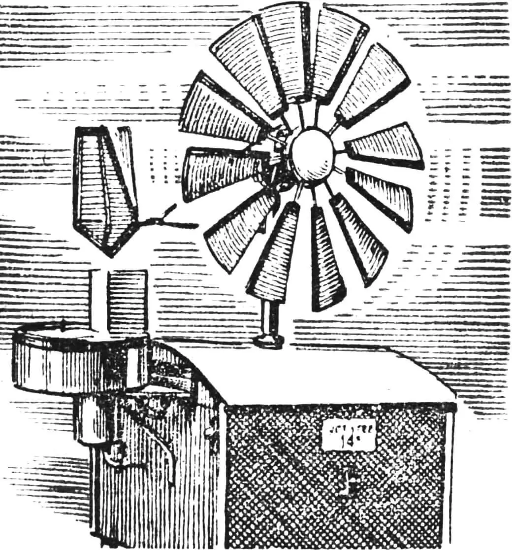
A box (Fig. 2) measuring 490X370X360 mm with several sensors is located on the school roof. An electrical cable connects it to the measuring panel (see photo), which is located in the geography classroom. Recording instruments are placed on the 450X300X150 mm panel.
WIND DIRECTION INDICATOR
A weather vane is mounted on a metal rod Ø 15 mm and 500 mm long, which is set according to wind direction. Its lower end is connected by a link to the sensor shaft — a ring potentiometer (Fig. 3). Its three brushes, located at an angle of 120°, are connected to three phase windings of the recording device. Following the weather vane, the potentiometer “reacts” to changes in wind direction, redistributing current in the stator phase windings: each position of them on the sensor potentiometer corresponds to a certain position of the magnet-rotor relative to the phases of the recording device stator.
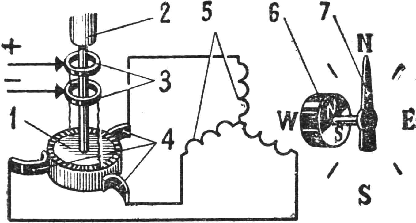
1 — ring potentiometer, 2 — weather vane rod, 3 — contact rings, 4 — contact brushes, 5 — stator winding, 6 — rotor (permanent magnet), 7 — pointer and scale.
A pointer is mounted on the magnet-rotor axis, which rotates with it and shows the wind direction.
A magnetic compass is mounted on the side wall of the sensor — for orientation by the cardinal directions.
The installation angle for the external device of our station is 14°.
WIND SPEED INDICATOR
The principle of a magnetic tachometer device is the basis of its operation (Fig. 4). The generator-sensor is mounted on the weather vane rod. An impeller Ø 560 mm is located on its shaft — it rotates the shaft at a speed depending on the wind speed.
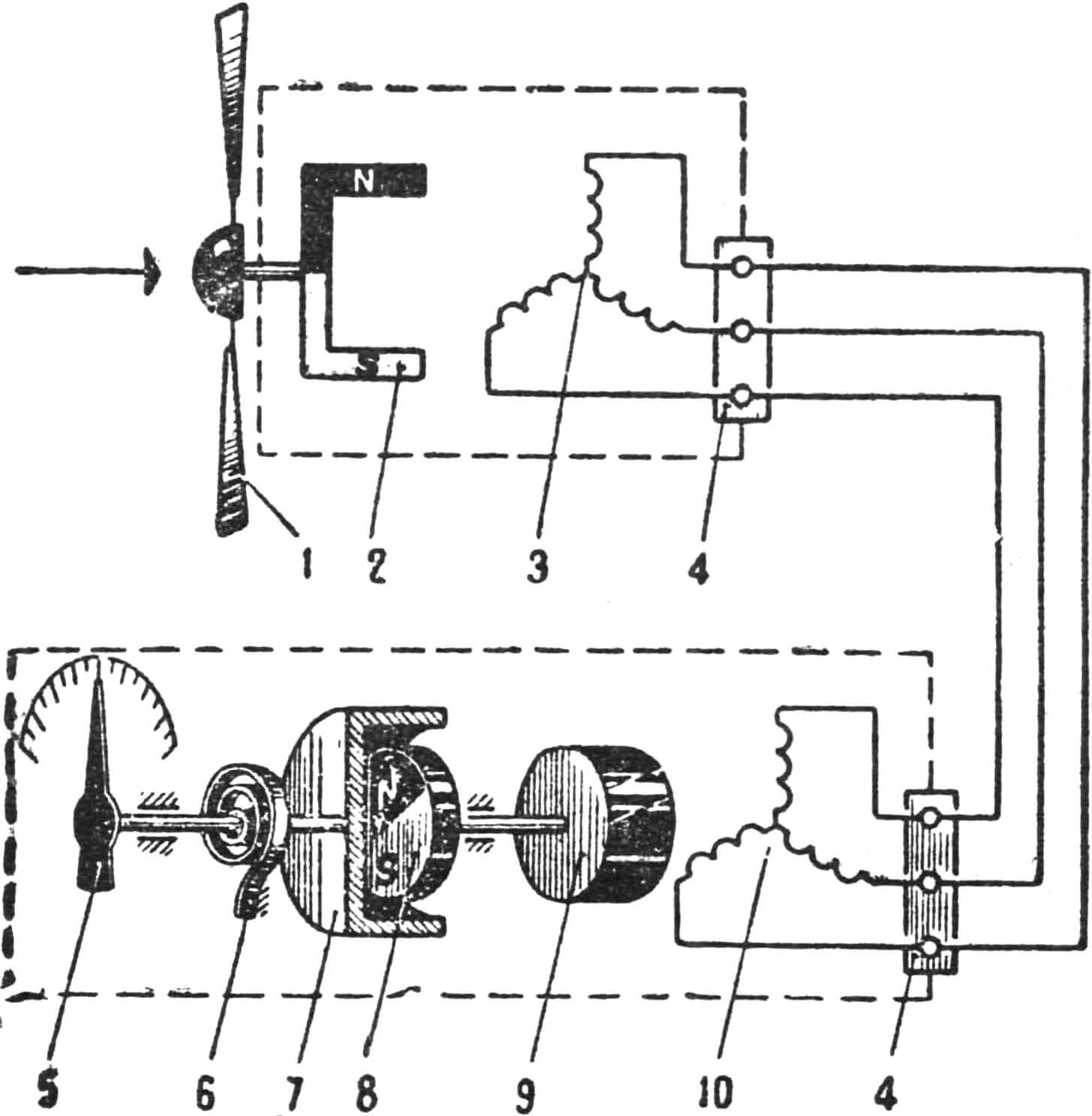
1 — impeller, 2 — rotor, 3 — stator winding, 4 — plug connector, 5 — pointer and scale, 6 — spiral spring, 7 — copper cap, 8 — permanent magnet, 9 — electric motor rotor, 10 — electric motor stator winding.
The current generated by the generator-sensor flows through the current collector via wires to the stator winding of a synchronous electric motor placed in the recording device. There, a rotating magnetic field is created, under the influence of which eddy currents arise in the short-circuited rotor winding, and it begins to rotate.
A permanent magnet located on the rotor shaft induces the same currents in the sensitive element — a copper cap. The magnetic field that arises in this case performs mechanical work — rotates the cap, and with it the pointer of the recording device. A spiral spring counteracts their continuous rotation.
The wind speed can be determined at any time of day by the instrument scale. The scale calibration in m/sec was performed using an anemometer and a stopwatch.
RAIN GAUGE
is designed to determine the amount of precipitation in mm that has collected per day in a reservoir Ø 250 mm and 100 mm high. It is made of sheet metal (Fig. 5) and coated with waterproof paint. A smaller reservoir Ø 79 mm and 100 mm high is installed underneath it. The amount of water occupying 1 mm of its height in the first vessel occupies 10 mm in the second.
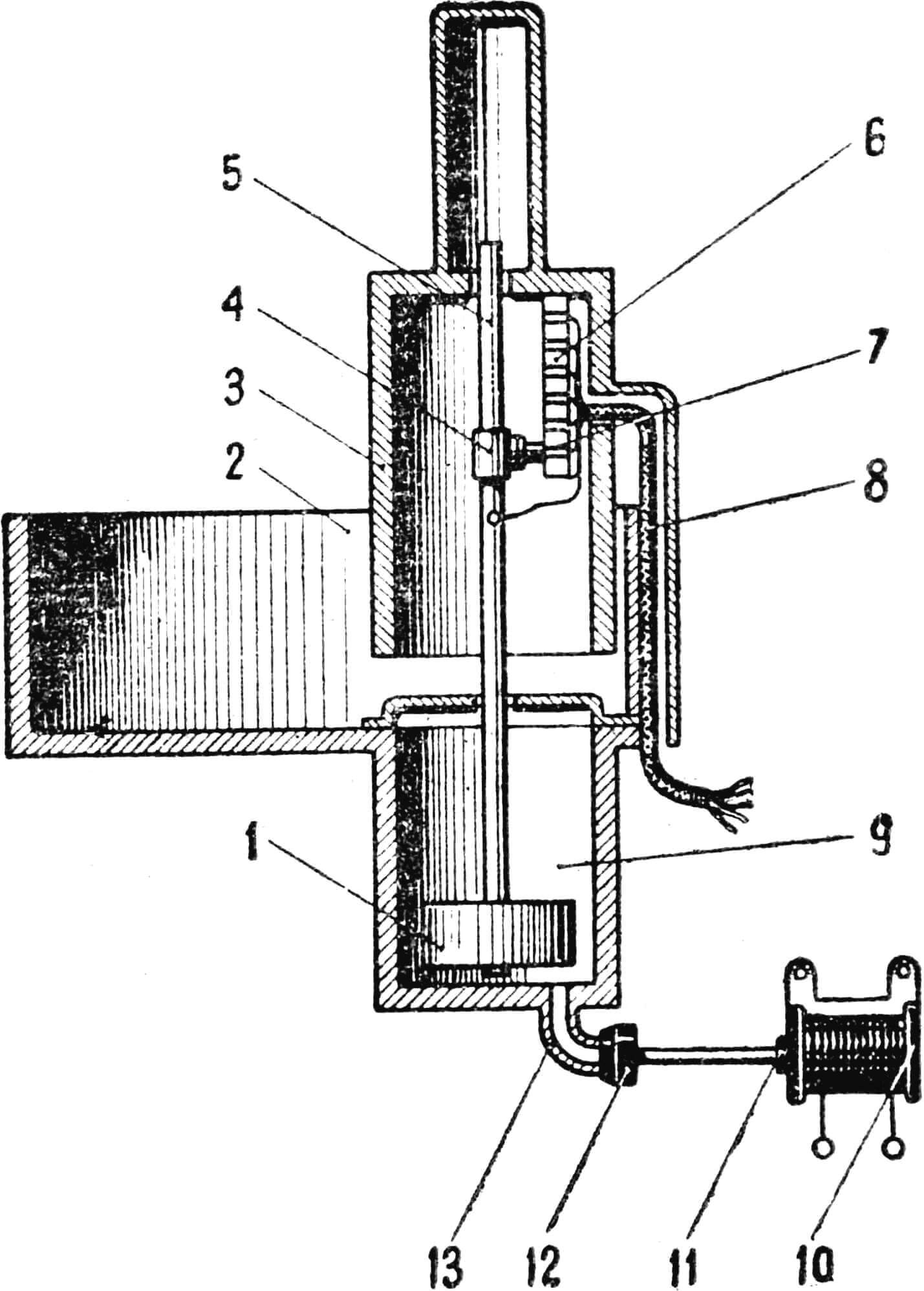
1 — float, 2 — large reservoir, 3 — protective housing, 4 — brush holder, 5 — rod, 6 — contact panel, 7 — carbon brush, 8 — cable, 9 — small reservoir, 10 — electromagnet, 11 — electromagnet armature, 12 — valve, 13 — drain tube.
A foam float with a rod is located in the small reservoir, on which a carbon brush is mounted. The latter slides along a vinyl plastic panel on which contact lamellas are mounted. They, in turn, are connected by an electrical cable to the signal lamps of the measuring panel. The rain gauge contact system is protected from water by a housing. Each signal lamp corresponds to a certain amount of precipitation in mm.
A special valve device allows draining water from the reservoirs without leaving the room. By pressing the “drain water” button, we activate the electromagnet and a rubber valve mounted on its armature.
OUTDOOR AIR THERMOMETER
The principle underlying its device is the dependence of electrical resistance on temperature (Fig. 6).
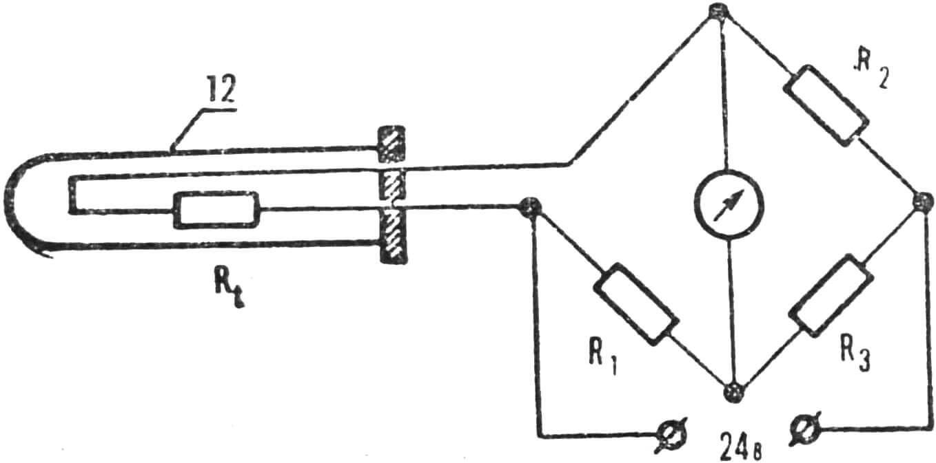
The scale of the magnetoelectric logometer is calibrated in Celsius. The device itself is connected in a bridge circuit consisting of four arms (R1, R2, R3 and Rt). The first three are made of manganin, a material that practically does not change its resistance with temperature changes. The Rt arm is made of copper and placed in the measured medium. The metal housing in which it is located is mounted on the external device and covered with a housing painted white — to reflect sunlight.
The circuit is powered by a 24 V DC source. Current will not flow through the measuring instrument connected in the bridge diagonal only under one condition: if the products of the resistances of opposite arms are equal, that is R1 * R3 = R2 * Rt. On the instrument, this corresponds to a temperature of 0° C.
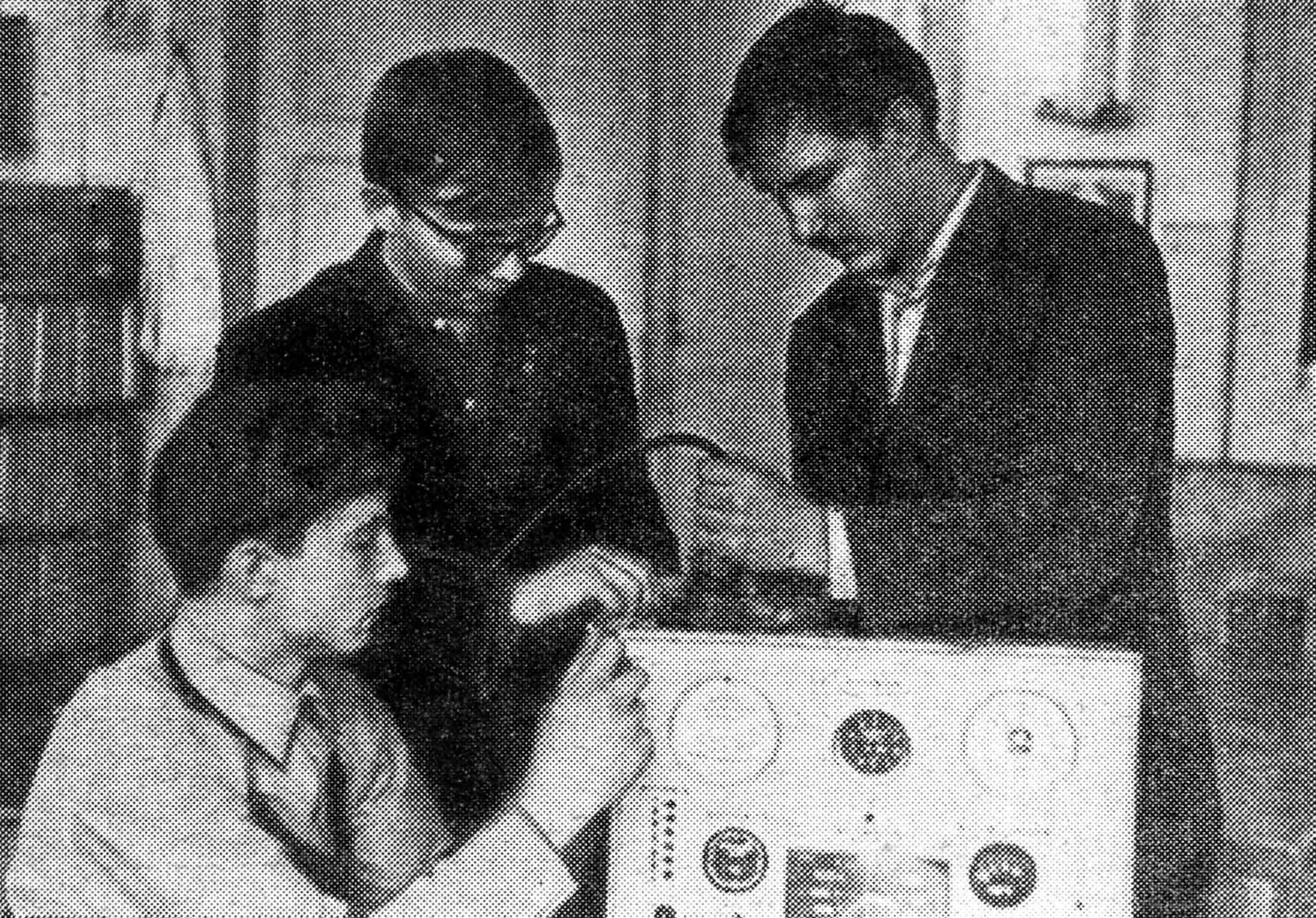
The measuring panel contains electronic clocks, a barometer, a thermometer that determines the indoor air temperature, a hygrometer, a psychrometer and a calendar. The panel is illuminated by fluorescent lamps. Power supply at 24 V is provided from a 220 V AC network through a step-down transformer and a rectifier device — they are located inside the measuring panel.
Our automatic hydrometeorological station is convenient and simple to operate. And cheap — we spent a minimum of funds on it (25 rubles for the purchase of clocks, a barometer and some materials). Mainly, decommissioned aviation equipment was used: instruments, switching and protective equipment, signal lamps.
L. YAKANIN, head of the school automation and telemechanics club
Recommend to read
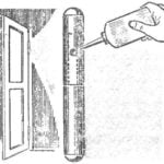 TO LOOP DID NOT SING
Get a new apartment, faced with such unpleasant phenomena as a creak of door hinges. Tried, removing the doors and hinges lubricated to eliminate the defect, but there it was. It turned...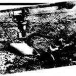 PLOW MOTOLIBERTY
Now an extremely acute problem of processing individual land plots. The horse would plough the field! But where are these loshadke? Motor-block to replace? Well, if you believe the...
