
 Adjusting the temperature of the local heating using the original heating element. The idea of local heating of a small area is implemented with the help of available details that it will probably in the reserves prudent owner, including, of course, owned and hams. Moreover, as the heating element applied to ordinary fixed resistor with a power dissipation of 2 watts. Depending on the power and resistance of the constant resistor can be achieved heating limited site to a temperature of -40 °C or even 60 °C.
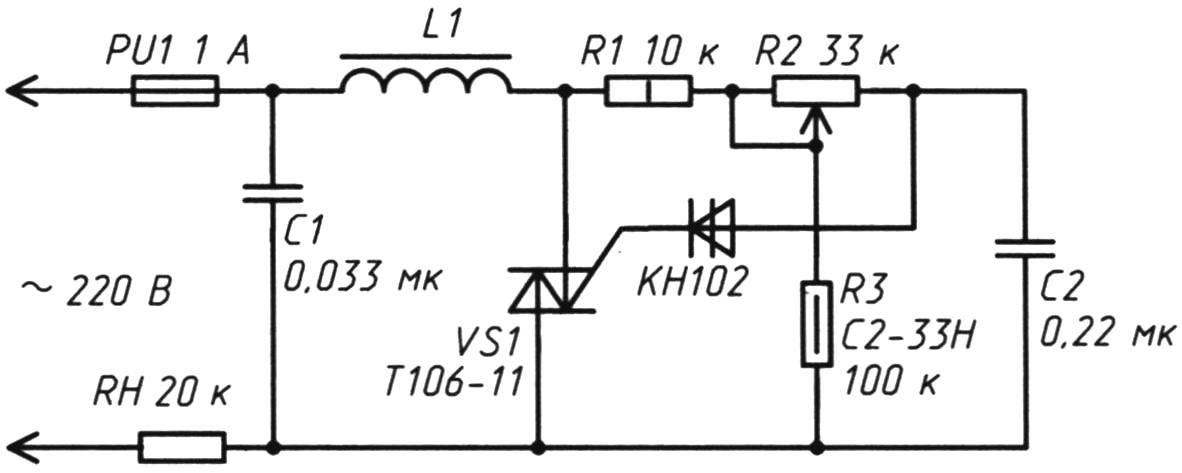
The scheme presented in Fig. 1.
Electric circuit device comprises a heating element R2, the led indicator HL1 and shunt resistor R1. The latter protects the LEDs from voltage fluctuations. In this scheme, led HL1 (it can be inserted in any direction as the current in the lighting network 220 V – AC) performs the role of the indicator device States, because if the heating element fails, the electrical circuit is open and the led will turn off. In addition, in my design it blinks (with a frequency of 50 Hz) is quite comfortable, as an additional health indicator of the network.
However, if someone such indication may seem redundant in the already simple scheme – feel free to delete from the circuit elements R1 and HL1; that its efficiency will not decrease.
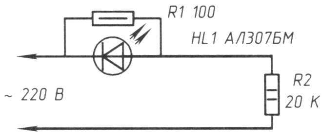
Fig. 1. Electric circuit device of the local heating
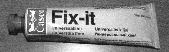
Fig. 2. Glue Fix-it sticks together so well that the design after it is applied is kept the gap the weight to 120 kg
If specified in the diagram the values of a heating ceramic plate to a temperature of 40°C is reached 7…8 minutes. After 10 minutes the temperature stabiliziruemost in the range of 50…55° C.
In this design, which can be taken as an example for deeper developments in practical application of ideas – the heating element is glued with heat resistant adhesive Fix-it (Fig. 2) in the center of tiled plate size 2×3 cm on the reverse (back) side.
Why is this glue?
No other glue has after drying such a “powerful” character; he can glue even… stones, suitable for bonding most materials, adheres well to wet, cold and painted surfaces. Adhesive bonding is elastic, resistant to water and frost (ambient temperature (-40 °C) and heat (+100 °C), that is, withstands heat.
Tested by gluing pieces of metal, rubber, leather, wood and other materials.
Why this design chosen tile? It is good heat conductive material that meets all standards of electrical safety (electric current is not conducting, refractory, solid, small area of tiles is difficult to split). Therefore, touching the tile from the side opposite to the installation of electric wires and the heating element, absolutely safe for human and animal. On the other hand (front) tile has a smooth polished surface, which gives the opportunity to fantasize about the practical application of the device, as will be discussed below.
Perhaps the only limitation that still would have left – such a construction should not be placed in a liquid medium (to avoid conduction current). In any other environment and in the quality of the solution of the local heating it, perhaps, will show their best of universal quality.
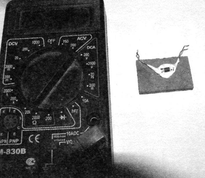
Fig. 3. View glued on the back side of the tile resistor R2
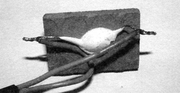
Fig. 4. A view of the connecting conductors to the heating element, resistor
In Fig. 3 shows a view of the glued on the back side of the tile resistor R2.
In Fig. 4 shows the views connected to the resistor wire.
Based on the electrical diagram (Fig. 1) and the low power consumption I applied a two wire SHVVP 2×0,75 mm2. Its length from the outlet to the place of installation of the tile plate with resistor and 2.5 m. considering the small power design, the voltage drop in the wires is negligible.
Fig. 4 is presented to the readers is no accident. For reliability and avoid the risk of infringement of contact with prolonged heating, the connecting wires beforehand not only obluzhivayutsya (opasayutsya), but are twisted with the conclusions of the resistor R2.
DETAILS
You need: tiles (5 mm thick), constant current limiting resistor 100 Ohm as a shunt for the safe operation of the led indicator, permanent resistor 17…20 ohms and a power dissipation of 5 W as the heating element connecting wire SHVVP (or equivalent), a led current up to 10 mA (fits almost any) and adhesive Fix-it (or similar). The area of the tile one described heating element may be – as in my case, 2×3 cm; for this purpose it is appropriate to cut using a special tool tile.
The resistance of the resistor 18…20 ohms suggests, and is confirmed by the practice (according to Ohm’s law) that the total power consumption when switching on the device in the lighting network 220 V will reach about 4W. Accordingly, the radio Amateur is deprived of the opportunity to install in parallel (in the diagram, Fig. 1) several of these resistors. Heating capacity and power consumption while growing, but the heating area, too.
As R1 use MLT-0,5, as R2 – MLT-2. Led – any current 10…15 mA.
Prospects of application of the described development is quite broad and limited only by the creative imagination; who has it is the place to be.
In my household, local and safe heating is used for heating of the substrate under the aquarium in the winter (on a platform of 0.5 sq. m. connects 8 — 10 resistors), the surface of the desktop that is installed on the balcony (in winter, quite cool, despite the glazing). If the back side of the tile to install a powerful wire type resistors, PEVR (or similar) and reinforce the wiring, the tiles may be heated to from 220 V to temperature, and 70 and 80 °C, and for a very short time. But then declared in the first lines of my description of the economical development will cease to be such.
Another idea of application development in that it is without any alterations appropriate to use as a fumigator. If on a heated tile to put the plate for the fumigator, then the whole structure will act as a mosquito repeller (in the summer) from the premises. Only in this case the plate of the fumigator can not put one in any place heated table (any surface) that makes the proposal more convenient to use than, for example, state or industrial plug-in vaporizer.
However, remember that the practical applications of this design are not limited, and can be found in the minds of radio Amateurs and more refined way.
But that’s not all.

Fig. 5. Schematic diagram of the temperature controller of heating
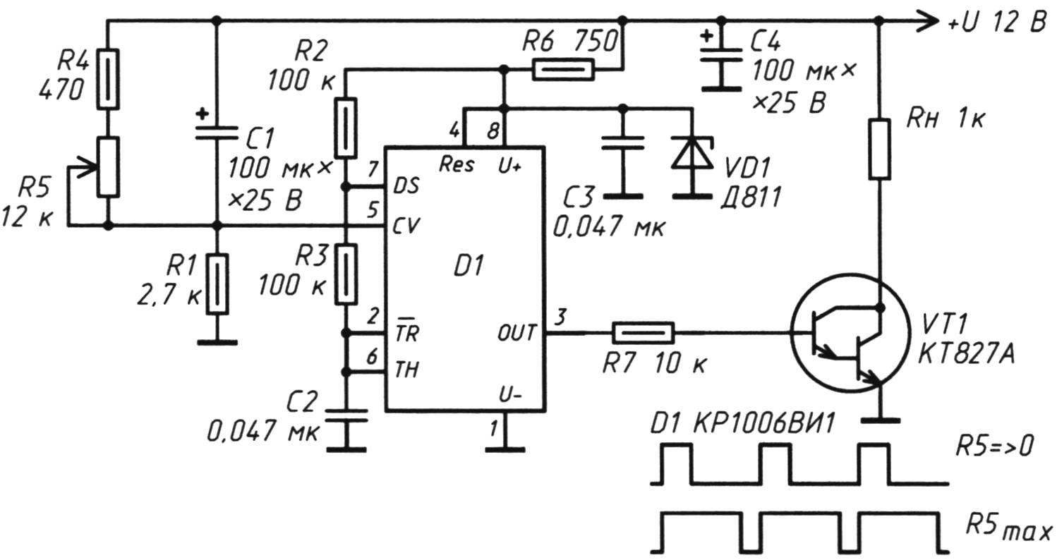
Fig. 6. Electric circuit with a 12V supply, empowering warm “table”
Now on two different examples, let’s look at how you can adjust the temperature of the heating resistor when connected to 220 V and “safe” constant voltage of 12 V. In this case, the heating temperature of the ceramic plates (tiles) directly related to the voltage drop across the resistor RL (scheme in Fig. 5 and Fig. 6).
MANAGEMENT OF “CERAMIC” HEATING IN THE LIGHTING NETWORK 220 V
In Fig. 5 is a circuit diagram of the heating device with the control element is a triac.
When a large current through the heating element (and other devices with the reactive nature of the load) such a device will create interference in the radio and electrical networks within a single electric circuit (electric meter energy). On the other hand, proposed in Fig. 5 arrangement, in my opinion, is distinguished by its simplicity and efficiency. As a control used a powerful triac, which is in the open state, flows into the load, both half-wave AC voltage. Choke And (45 turns of transformer wire PEL-0.8 to ring 2000НН) and the capacitor C1 smoothes the ripple voltage in the moments of incomplete opening of the triac near zero, which has a positive effect on active load. What I mean by this phrase?
The control voltage at the triac is a variable resistor R2 (SPO-1) with a linear characteristic of resistance changes (the index).
The device is designed for adjustment of the load voltage with power up to 100 watts. Within these limits the triac on a heat sink no need to install.
The body and knob of the variable resistor (for security use) must be isolated. Because the node elements are connected to a life-threatening voltage when in use, the device should comply with security measures.
I should note that this scheme is taken from industrial devices -dimmer, which sell well in retail ten years ago. To save time experiments “ceramic heater” I was conducted an experiment with this scheme (instead of RL as conceived by the manufacturer’s included bulb power 11-60 W). However, the device is tested and showed good results: maximum heating resistor R h is achieved in 4.5 minutes. At the maximum increase in the resistance of the resistor R2 the voltage drop across RL is only about 10 V (AC), and it is not heated. In principle, the elements L1 and C1 in certain cases can be deleted from the scheme.
The device is in adjustment is not needed.
Fixed resistors type MLT or C2-33. The limiting resistor R1 with a power dissipation of at least 1 watt. The triac can be replaced by КУ208В-КУ208Г.
The capacitors C1 and C2 of the type of MBM, MBGO, or equivalent to the working voltage is not lower than 300 V.
AT 12 V POWER SUPPLY
“Warm table” according to the scheme in Fig. 6 with a power supply of 12 VDC has two aspects – on and off. A small voltage is selected for the maximum safety of work with the device. With this simple scheme can significantly expand the capabilities described above, the original heating element.
In schema-based popular КР1006ВИ1 timer that is enabled as a pulse generator. The duty cycle of the IC output (pin 3) can be adjusted by changing the bias voltage on pin 5 is D1. This circuit design has received the name of pulse-width method of changing the output signal.
In the electronic control scheme introduced a stabilization circuit consisting of the elements R6, and Sz of the Zener diode VD1. As a last desirable to apply any of the existing semiconductor devices with voltage stabilization 9V. The current consumption of the chip D1 is in the operating mode less than 10mA, therefore, the use of “simple” Zener justified. Electrolytic (oxide) capacitor C4 smooths out low frequency ripple on nutrition.
Chip D1 when the power generates electric pulses of rectangular shape. Pulse frequency is determined by the values of the elements of the timing circuit R3C2. The smaller the capacitance of the capacitor C2, the higher the frequency of the pulses at the output (pin 3 D1). Resistors R1, R4, R5 form a voltage divider with the ability to adjust. The capacitor C1 ensures a smooth change of the duty cycle of the rectangular pulses. The shape of the pulses shown in Fig. 4. Compound transistor VT1 opens every positive edge of the rectangular pulses coming to its base through a current limiting resistor from the output of the chip. The fill factor of a pulse sequence varies, depending on the resistance of the voltage divider at the input D1 of about 35 to 100 %.
Therefore, the voltage on the heating element increases in proportion to the decrease in the resistance of the variable resistor R5. The resistance R5 is 1 kω or less, the voltage across RL is maximum.
Electrolytic (oxide) capacitors of the type K50-29 on the operating voltage of not lower than 25 V. the Remaining capacitors in the circuit of the selected ceramic or of type KM. Instead of a transistor controlling the heating element, you can use the device КТ834А-КТ834В.
Composite transistor /T1 must be installed on insulated from the mass of the car radiator. This will increase the security of electronic elements and the reliability of the whole node during long-term operation. Recommended electrical parameters of the transistors such that the entire Assembly has the necessary reserve performance; judge for yourself: maximum power dissipation КТ827 and КТ834 – 100 W; the maximum allowable current through the junction collector-emitter data, the composite transistors 5 and 8 A.
Currently, the device passes the test.
A. KASHKAROV
Recommend to read
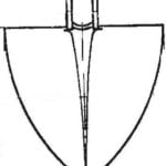 ONE BY TWO
It turns out that a shovel with a folding bayonet can be useful not only for tourists but also for gardeners. A different constructive solution of the node folding shovel will give... BUILDING A BUNGALOW
"What kind of terem-teremok is this? It's not low, not high..." The dimensions of the house are indeed small, but, looking at the adjacent descriptions and diagrams, you will see that it...
