ACROSS THE FIELD SWEEPING PLOUGH

THE FIELD IS SWEEPING THE PLOW
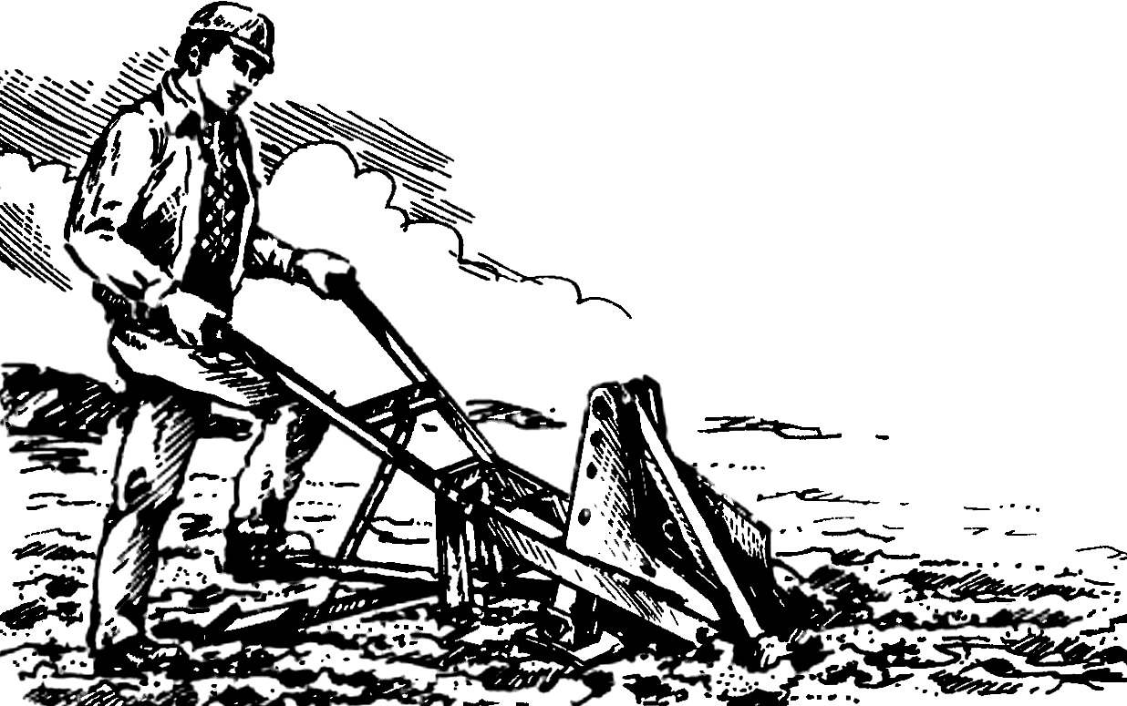
We offer our readers the plow rather unusual. It is not necessary to pull forward, neither a horse nor a tractor, and the now familiar motor-plow is selhozgodu clearly does not. It has no motor, however moves together with the farmer down the furrow. Not continuously but as steps. The fact that the drive in him — a foot, lever. Alternately pressing on the pedals, the farmer moves the stops, pushing the body of the plough cybertigeranime jerks on the treated land. Traditionally, that seemed to be unified, the process of plowing divided here into two separated by time subcycle: “trim” and “blade”. The design of the rotary blade with variable profile allows to reduce the drag of the soil by “pruning”, as well as to improve ergonomic features and the second subframe.
The plough is convenient for work in small areas or in cramped conditions mistwalker spaces of the garden. Such a mechanism is ecologically clean and unlike the “engine brothers” is having a detrimental effect on the environment. Plowing with it is transformed into a kind of sport exercises on the foot shell simulator. The plow is recognized as invention and protected by the copyright certificate of the USSR.
 
The idea is to create a plow that wouldn’t need the motor and operated by the farmer, — stirs me to admit, not one year. Gelled and the specific technical solution working body: Coulter field Board and a rotary blade. But the drive, or did not work.
 
A clue found in nature: the features of movement caterpillar-surveyor. The principle immediately tried to implement in the specific mechanism. As a result, a design “step” of the plough, is here presented in the figures. It consists of three functional units. First of all, the body of the plough, which include the ploughshare with podnebesnya, field and thrust Board, the rotary blade and brackets. The second functional unit to form the arm with two wooden covers, corner bar located in the middle of the block and elements of the fastener. Finally, a foot lever actuator — the primary site walking plow. He presented the following items: two pairs of cheeks attached to them (parallel to each other) left and right supporting rods pivotally connected with the support plate; siloWai rod with the guide bracket; left and right pedals pivotally mounted on the ends (respectively) of power — from raskoshnoe and dump levers; connecting the cable, the axis of rotation (toes) and the rollers (one at the end of the dump, and two on both sides of the power levers). For transportation of the whole structure of the plow in hard ground to the place of work is provided by three-wheeled transport cart.
 
The work of the plough says in illustrations scheme. Initial state: the support rod is tightened to the housing. Pedal power lever is at the top, and dump the pedal at the bottom.
Lifting the plow by the handle, the Plowman guides the toe of the blade in the ground. Holding the arm at the same level above the ground, performs a sharp push with your right foot on the power (right) pedal to the metal. Crashing into the ground, the plow is moved by 0.2—0.25 m forward. The blade is tilted, turning on the hinges. The drag of the soil is reduced, making it easier to execute subcycle “trimming”.
 
Then the farmer crosses with the left foot forward and shoots right off the pedal. Holding the plow by the handle, sharply presses (but with the left foot) on the left — otvalnuyu — pedal all the way to the ground. Turning on its hinges, the blade takes the “cool” position, pushing and turning over the ground – completes the subcycle of “blade”.
 
Alternate pressing of the pedals and the installation by using the arms the desired depth of plowing and formed the furrow. Crossing together with a supporting rod in the formed furrow, the Plowman is moving forward at a speed of about 7 m/min In contrast to the work with a plow horse is not required to attach to the arms considerable effort (horse-drawn plows — 50 kgs!). The process of plowing becomes useful and valuable for combat sports physical inactivity exercise (like training on a stationary bike).
 
With regard to the transport of the plow in hard ground to work, there are also difficulties arise due to the trolley of special design. The plow is lifted by the handle, abutting end of the blade in the ground. Then, combining both fingers truck with holes in the housing, put the plow on the fingers. The force depleted and the levers will be located on the traverse carts. The supporting rod with a support move for yourself, and you can move.
 
Plow with foot lever drive.
A plow with a foot lever drive:
1 — body of the plough, 2 rotary blade 3 to the base plate with the supporting rod 4 to the power lever with raskoshnoe, 5 — dump lever, 6 pedals, 7 — wire, 8 — unit (diameter of the circle 50 mm) on the crossbar between the handles, 9 — wood pads, 10 — handle, 11 — dimensional and (parallel to it) uvalno-dimensional brackets, 12 — cheeks (2 pairs), 13 — power bar, 14 — clip 15 — clip guide, 16 — spacer (2 PCs.)
 
Scheme of operation of the foot lever drive (numbering of the positions in Fig. 1).
The scheme of operation of the foot lever drive (numbering of the positions in Fig. 1).
 
Manufacturer of plough, foot operated it is advisable to start with the hull. Due to the fact that to work it needs to be in the most difficult conditions, the construction should meet special requirements. In particular, high strength, rigidity, ability to withstand dynamic loads, abrasive properties of the soil. Hence, the materials should be used here are appropriate.
 
For the manufacture of hard Board, podlesnik, brackets can, for example, be limited to such a mark, such as Steel 20; but for the blade, blade and field Board need special jointers steel (say, Л65, Л53) or high-quality bearing (SHKH15), processed but technology that sufficient detail was contained in the third issue of “M-K” for the year 1991.
Size, configuration of body parts, their relative position is clear from the presented illustrations. So prepared, experienced homebrew fabrication and Assembly of construction but will be quite capable. Beginners, probably, it is better to use ready housing (for example, from the right of a plow horse). adapting it for the design. The least amount of work require plows in the “left” version (they have the soil, as in selhozarteli, is on your left as Plowman way). Only here produced very little.
 
Well, if a homebrew has been riding the plow with the less convenient for the worse case (say, of type PX-25 or PX-23) to get upset, too, there is no reason. It is possible to adapt to such a construction, when the main load when plowing on the left leg. Moreover, for lefties is the best option.
 
Adjust the plow horse (and similar buildings) to the proposed design with quite reasonable for practice the results by typing in the described scheme accordingly. First of all changes the most important parts. In particular, it is necessary to move and consolidate symmetrically relative to the vertical plane of the field and resistant Board, ploughshare and moldboard. You must also deploy the toe from right to left and top down podlesnik. After completing the last holes (the holes in the blade and the ploughshare, unless they coincide), connect accordingly the details.
 
Will also have to swap depleted power and leverage. In this regard, there is a need to adjust properly the location of the brackets. moreover, overall and uvalno-dimensional, with the change of places and change the direction of the bend. In the guide bracket are grooves-the window to “mirror” the display. And the blade is made of additional support (for holes) and fixed on uvalno-dimensional bracket.
 
It is easy to see that the blade is stationary relative to the plow blade. And this design would inevitably entail an increase (10-15 kgs) effort, which should be applied during operation of the plow to force the drive pedal. The disadvantage of this can be avoided by running between the shingles and the blade relative to the corresponding joints. In this case, additional support for the blade no longer exists.
 
Pitch of the blade.
The sweep of the blade.
 
Swivel blade.
The rotary blade (hardness on the breast and wing 50 HRCe):
1 — the profile of the bending blade, 2 — ball joint (4 PCs.).
 
Ploughshare.
The blade (the hardness in the hardened zone 41,5 53,5 HRC…uh).
 
Podlesnik.
Podlesnik.
 
And one more remark. When executing the body of the plow in the “right” option it is important to note that a chamfer, countersink holes near the blade are made other than shown in the illustration side. However, the same applies to the implementation of the skew, curve and guide pivots from the blade.
 
The body of the plough (with the brackets).
The body of the plough (with brackets):
1 — field Board (Steel 20, the thickness of sheet 4 mm), 2 — shingles (Л65 Steel, plate thickness 7 mm), 3 — podlesnik, 4 — pivoting blade (Steel Л65, sheet thickness 5 mm), 5 — ball joint (4 PCs.), 6 — resistant Board (St3, sheet thickness 4 mm), 7, 10 — dimensional brackets, 8 — strength bracket, 9 — otvoreno-dimensional bracket, 11 — guide bracket 12 — M10 bolts (the nuts are screwed after the installation of the handles), 13 — plate with hole for mounting the transport truck (Steel 20, 2 pieces), 14 — pin (Steel 20, a diameter of 20 mm, 2 pieces) 15 — washer (8 PCs.), 16 — pin (4 PCs.).
 
Right-cheek — 2.
Cheek right — 2 PCs. (left cheek — piece 2 “mirror” version with opposite location of bends and countersink).
 
Power lever (with raseinai).
Power lever (with raskoshnoe):
1 — sleeve (St3, Øh 30 mm Øin 16 mm, length 33 mm), 2 — rectangular cross-section tube 40X30X3 mm, 3 — tube (cross-section 30X30X3 mm), 4 — pin (Steel 20), 5 — lug cable (the end — thread M8).
 
Transport truck.
Transport cart:
1 — the base (welded, from segments of square tubing with a wall thickness of 3 mm), 2 — axle (Steel 20, a diameter of 20 mm, length 75 mm), 3 — wheel (3 PCs.), 4 — washer (4 PCs), 5 — pin (4 PCs.), 6 — pin (Steel 20, a diameter of 20 mm, 2 pieces), 7 — rear axle (Steel 20, a diameter of 20 mm).
 
After the work on the hull completed, you can start making treadle plow. Strict compliance with all dimensional requirements here will allow you to avoid trouble, any inconsistencies with the drive Assembly during its operation.
You should pay particular attention to the pairwise mounting of the cheeks to the support rods and spacer sleeves. The screw heads should be here are flush; then each of the two resulting parallel racks-scenes held together by these screws can move freely, without jamming: left — uvalno between size and power, and the right — between the power and the right marker brackets. In addition, there is also no interference and moving between the uprights-the scenes power lever and a power rod, the upper end of which pivots on zaspirtovanny axis (Steel 20, Ø 20 mm, length 140 mm), and the lower on my finger (the same material and diameter, but length 160 mm) inserted into holes of the power bracket on the destruction of 110 mm from the thrust of the Board. On the other the same finger, located parallel to the first fixed (with the possibility of rotation in the power bracket) end of the power lever.
 
Dump lever is mounted so that, once clamped between the left marker and uvalno-dimensional brackets can be rotated. Axis is made of steel of the same gauge as the old, finger 50 mm length. On the contact with the heel of the blade the end of this lever is placed (again on the finger, different from the above-mentioned a length — 135 mm) roller. Latest outer diameter of 30 mm, a width of the working part 31 mm.
 
Themselves rods and levers are executed from steel pipes of rectangular cross section (GOST 8645-68) with plugs of any suitable material (last in the illustrations not shown). And the finger of power is recommended (to increase the rigidity and reliability of the whole structure) to weld simultaneously with the formation of a connecting seam, followed by the radii.
 
Of course, at the disposal of homebrew to the above-mentioned pipes may not be. Then for the bars and the dump lever and fit the other pipe of similar strength sections, and area, etc. profiles. And as the fingers and axes you can use pressed or warnie steel tubing of appropriate sizes. It is not excluded and other adjustments, replacement, dictated by specific local conditions. Just rush with it, especially when it comes to the power lever and other equally important and critical parts of the design, it is hardly expedient: try seven times — cut once.
 

Specifications plow:


Dimensions (including handles ) mm: 1670Х610Х820


Weight (without transport trolley), kg: 48


Performance (at ploughing depth 0.18 m), m2/h 200


Actuator: foot lever


The pressure on the pedal power lever (when ploughing depth 0.18 m), KGP


to work on light soils…..20


on average…………..35


heavy………….65

 
A. KUZNETSOV, inventor

Recommend to read

  • FROM WIND-UP TOYSFROM WIND-UP TOYS
    Children tend to be interested in what is inside their favorite toys. Often, after such a curiosity that remains is to throw away the "spare parts". Meanwhile, the gear mechanism of the...
  • AND THE SEX BEAUTIFULAND THE SEX BEAUTIFUL
    Painters love to tell stories about the master, who, fascinated by the coloring of the floor along the walls, not noticed as it stained everything around him and was unpainted on a small...