THE MODEL IS CONTROLLED BY LIGHT

THE MODEL MANAGES THE LIGHT
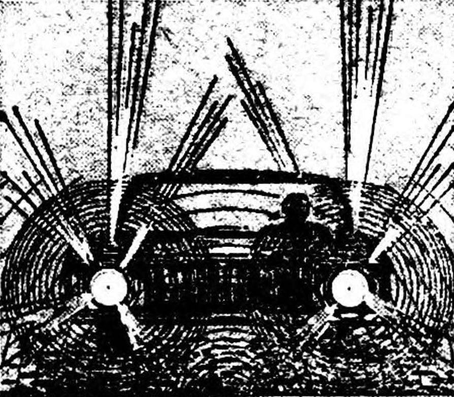
The electronic device described in mi readers, you can install on the toy, equipped with a separate drive for each caterpillar: tank, lunar Rover, Lunokhod. The model moves with headlights on in a darkened room, and set PA her the photodiodes capture the reflection of the headlights from obstacles. The appropriate commands to the drive engines on the basis of the received data takes the logical unit. Here’s how it works.

When the photodiode V1 is shaded, its resistance is high and, consequently, it creates a high potential which is fed simultaneously at the two inputs 1, 2 of the chip D1. Output 3 a logical 0, transistor V3 is opened and the relay K1 includes an electric motor.
 
The illuminated photodiode has a small resistance, the voltage drop across it is small. Therefore, the inputs 1, 2 is fed a logic 0, and the output 3 appears a logic 1: transistor VЗ closed, de-energizing relay K1 and the motor stops.
It should be remembered that the left photodiode controls the right tracks and the right photodiode — left. In this case, the model will turn away from the lighted obstacles.
 
If you disable relay K2 and swap photodiodes (left controls the left track and the right — right), the model will “seek a light”. And the dark it will go right, and when illuminated by a flashlight on one diode model will turn towards the source of light and head towards it.
 
The concept of photostrictive.
Schematic diagram of photostrictive.
 
Electric circuit models of engines.
 
Electric circuit models of engines.
 
Placing the lamp 1 and photoresistor 2 in the front body part 3.
 
The location of the lamp 1 and photoresistor 2 in the front part of the body 3.
 
Circuit Board photostrictive with the layout of the parts.
 
Circuit Board photostrictive with the layout of the parts.

 
The capacitor C1 serves to make the model for 0.5—1) continued to pull away from the obstacle, even when AC signals from the photodiodes. The resistor R7 wire, is used to maneuver back was performed with a turn and mo-
 
del turned away from the previous course. C1 and R7 are selected when establishing photostroika.
 
For best noise immunity, the engines should be powered from a separate source. Voltage photostrictive should not exceed 5 V.
 
Chip К155ЛАЗ can be replaced with any other combination of the four elements 2I-NOT. Transistors— MP40 — МП42 with any alphabetic index. Perhaps the transistor V4 becomes warm, as it includes two relays. To avoid this, pick up relay K2, short circuit minimum trigger current or loosen the spring contact system. K1, K4 — modified РЭС10 (passport RS4.524.304 or 315), K2, KZ — RES9 (passport RS4.524.203 PLI 214). Photodiodes FD-3 is better for
 
hange PA more sensitive photoresists of the type of SF. Then the device triggers at a distance of 10— 15 cm from the obstacle.
 
Correctly assembled device hardly needs establishing (sometimes required the selection of photodiodes) and works immediately after connecting the power supply.
 
B. SPLITVID, vorochilovgrad

Recommend to read

  • ROUND, BUT WITH CORNERS…ROUND, BUT WITH CORNERS…
    A scrap page torn from a magazine with a picture of a cute table to lay in the Park on a bench, I sat down to rest. Table, or rather his design, I was interested (in the old days I had...
  • “HORNET”, AKA “RHINO”“HORNET”, AKA “RHINO”
    The Polish campaign of 1939 forced the military leadership of the Wehrmacht to equip the troops of the mobile means of combating enemy tanks. In the same year the firm ", Alkett" created...