A strange situation has developed in our country: those who can afford to buy a tractor don’t need it (except perhaps for amusement at a country villa), while those who need a tractor because they live off the land cannot afford to buy one. But you can’t accomplish much on the land with bare hands without mechanization. So those who can’t do without a tractor are forced to build it themselves from still serviceable or restored units of old or abandoned equipment.
I’ve been interested in machinery since childhood, and I’ve had to repair quite a bit of it. Under the influence of publications in the “Modelist-Konstruktor” magazine and the developments published in it, I began to build some mechanisms myself. But as it later turned out — creating something of your own is much more difficult than restoring the operability of even a complex machine. Therefore, not all homemade devices turned out successful, but experience came, machines appeared, a welding apparatus, tools accumulated, without which one shouldn’t undertake creating a serious structure.
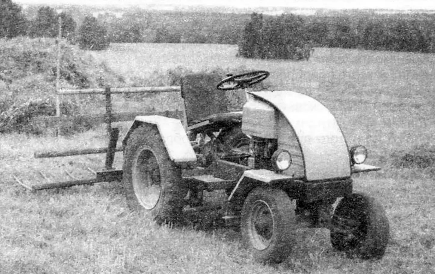
And my first such machine became a mini-tractor with a removable body of the “Unimog” type (a universal road-utility machine produced by the former GDR. — Ed. note). It worked for me for 13 years, but with the appearance of a truck, the need for it significantly decreased. Then I decided to build a more specialized tractor on its basis, intended only for agricultural work, which I present to the readers of the magazine.
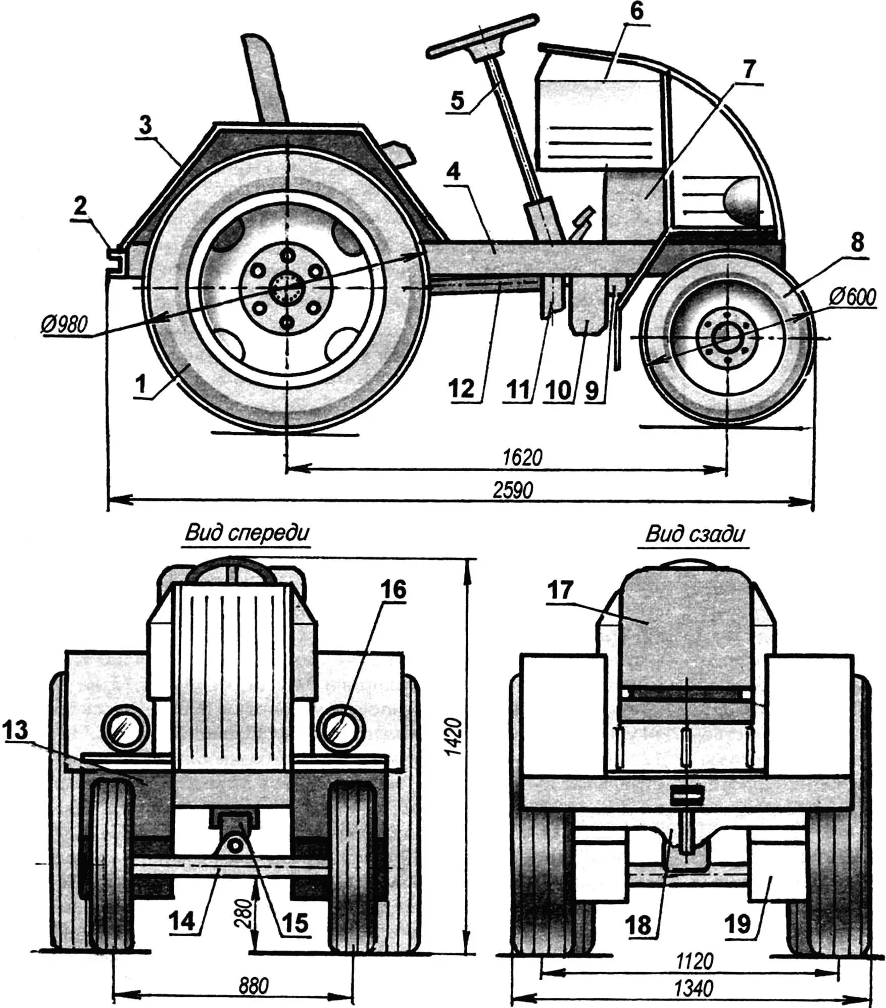
1 — rear wheel (from GAZ-53 car, 2 pcs.); 2 — drawbar; 3 — rear wheel fender (steel sheet s1, 2 pcs.); 4 — frame; 5 — steering; 6 — engine compartment wall (steel sheet s0,5, 2 pcs.); 7 — power unit, N=18 hp (from “Izh-Planeta” motorcycle); 8 — front wheel (from “Zaporozhets” car, 2 pcs.); 9 — chain drive housing (steel sheet s1); 10 — additional gearbox (from GAZ-51); 11 — brake drum (from GAZ-51); 12 — driveshaft (from GAZ-66, front, shortened); 13 — front fender (steel sheet s1, 2 pcs.); 14 — front axle (from electric forklift); 15 — front suspension fork (welded part); 16 — headlight (from industrial tractor, 2 pcs.); 17 — sprung seat; 18 — rear axle (from GAZ-51); 19 — front fender mudguard (rubber, sheet s5, 2 pcs.)
When manufacturing the tractor, the main attention was paid to the reliability of the design, but I also wanted its appearance to be proper, and to make it easy and convenient to work on.
All tractor units are mounted on a homemade simple trapezoidal frame (its front part is slightly narrowed relative to the rear). The frame base consists of two side members, as well as front and rear cross members (the latter also has cantilever extensions). Both the side members and cross members are made of rolled steel channel No. 12 (wall height — 120 mm, flange width — 52 mm). Two front cross members are also made from the remainder of the same channel. Auxiliary (non-load-bearing) frame elements are made from suitable rolled stock that was available at the time — mainly from angles of various sizes.
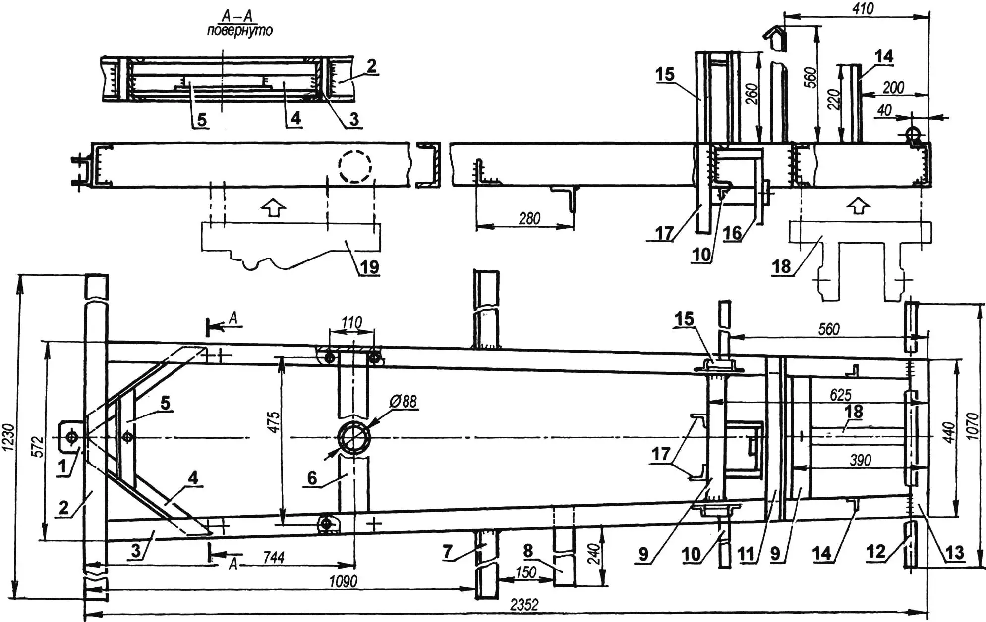
1 — drawbar eye (channel 180×70, narrowed); 2 — rear cross member (channel 120×52); 3 — side member (channel 120×52, 2 pcs.); 4 — diagonal brace (angle 45×45,2 pcs.); 5 — tie (angle 63×40); 6 — crossbar (tube Ø88); 7 — front rear fender support (angle 63×63, 2 pcs.); 8 — footrest (angle 63×63); 9 — cross members (channel 120×52); 10 — rear front fender support (angle 25×25, 2 pcs.); 11 — under-hood portal (angle 50×50); 12 — mounting cross member (tube Ø28); 13 — front cross member (channel 120×52); 14 — fuel tank bracket (angle 25×25, 2 pcs.); 15 — engine subframe bracket (angle 50×50, 4 pcs.); 16 — chain drive housing frame (angle 30×30) with bearing housing 203; 17 — gearbox mounting bracket (angle 50×50, 2 pcs.); 18 — front suspension fork (channel 140×58, channel 120×52); 19 — rear suspension shoe (channel 220×80, narrowed)
A subframe, several brackets and posts necessary for mounting the power unit and transmission units on it are welded to the frame. The engine subframe consists of two pairs of posts welded to the side members on opposite sides of the frame. The pairs are connected to each other at the top by ties. All parts are made from 50×50 mm angle.
Many holes of various diameters are drilled in the frame. Most of them are made in place during the installation of units and assemblies, so they are not shown on the drawing.
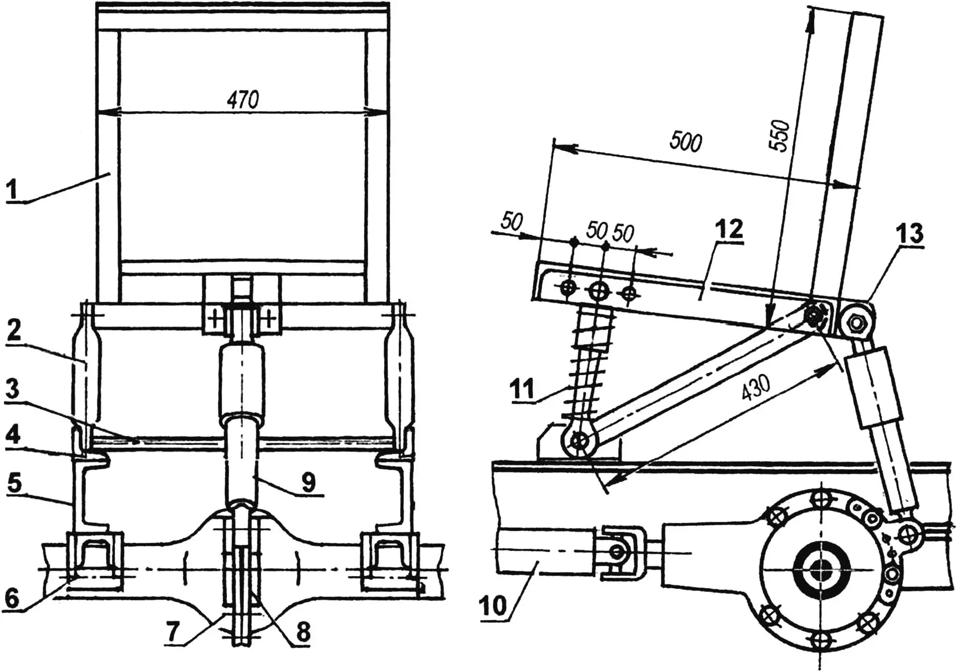
The rear axle is rigidly attached to the frame using shoes welded to the axle housing directly under the side members. Each shoe is bolted to the side member with four M12 bolts (two on each side of the beam). A bushing is welded to both shoes, serving to connect to the frame’s rear hitch, on which, in turn, agricultural implements are mounted, in particular a plow. For coupling the tractor with other implements (for example: horse-drawn rakes, cargo cart), a drawbar eye made of narrowed steel channel 180×70 is welded to the rear cross member. Implements are attached to the tractor with an L-shaped kingpin.
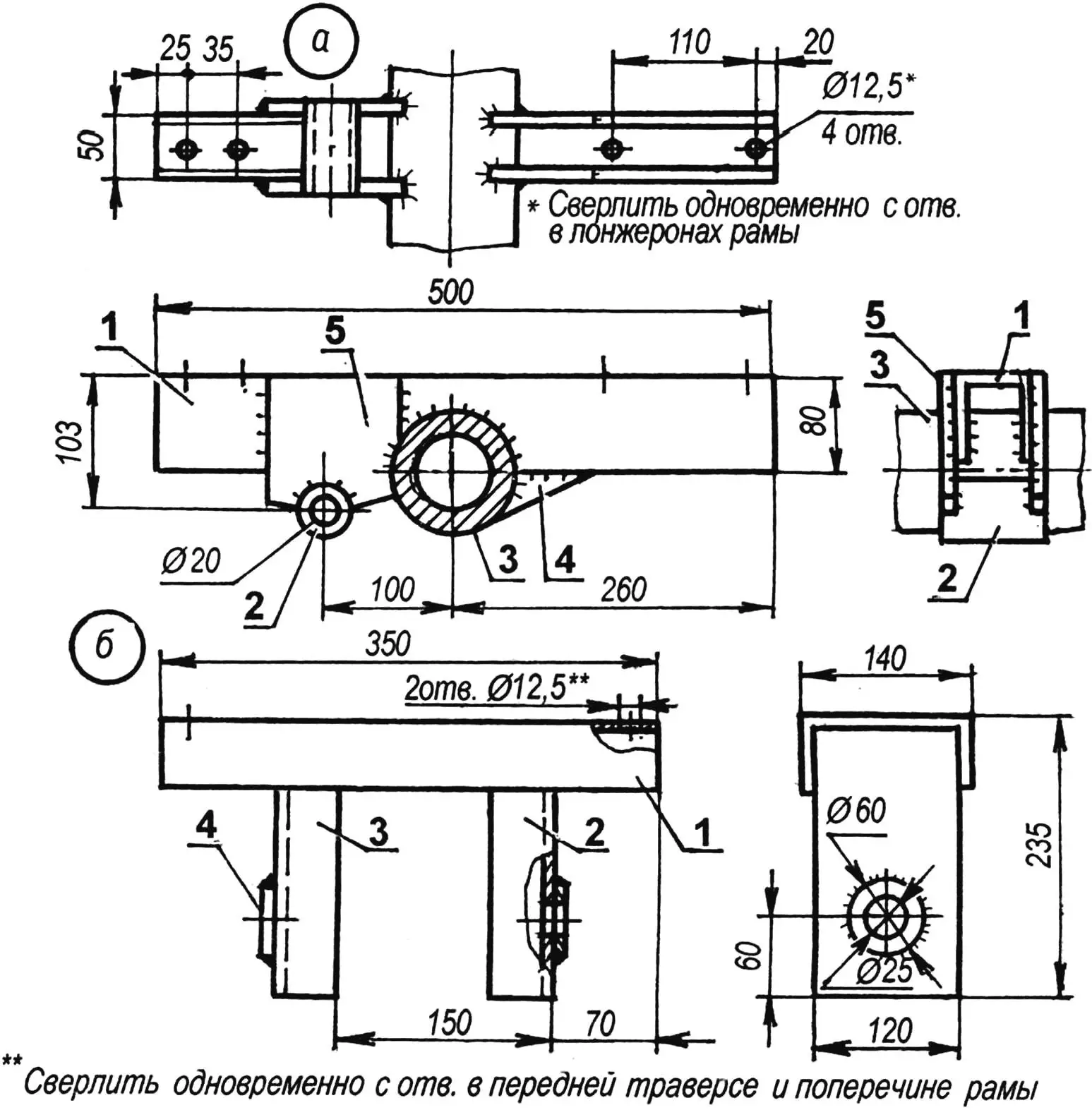
a — rear shoe: 1 — block (channel 180×70, narrowed); 2 — hitch connection bushing (tube 30×20); 3 — rear axle beam (housing); 4 — gusset (steel sheet s4, 2 pcs.); 5 — plate (steel sheet s4, 2 pcs.);
b — front fork: 1 — block (channel 140×58); 2 — front fork arm (channel 120×52); 3 — rear fork arm (channel 120×52); 4 — kingpin bushings (from KamAZ car hydraulic coupling)
The front axle suspension, although rigid, is articulated. For this, an eye is welded to the axle beam, with which the beam is suspended on an axis in a specially welded fork. The fork, in turn, is bolted with M12 bolts to the front cross member and cross member of the frame in the middle between the side members.
The power unit (combined: engine, clutch mechanism, gearbox) with a capacity of 18 hp — from the “Izh-Planeta” motorcycle with forced air cooling of the cylinder. The fan with housing was used from the SZD motorized wheelchair engine. To connect the units, I had to modify the cylinder — the vertical bridges connecting the cooling fins were removed from it, and the holes for the mounting studs were shifted along the same circle by an angle determined “in place.” On the cylinder head, I partially cut off the cooling fins, fitting it to the dimensions of the cooling housing. The engine is mounted transversely on the frame. The exhaust system is homemade, I made the muffler from a 10-liter fire extinguisher, filling it with metal shavings. Electrical equipment: generator, ignition switch, ignition coil — used from the “Voskhod” motorcycle.
Another (additional) gearbox — from GAZ-51 — is used in the transmission. The transmission of torque from the “Planet” power unit to the additional gearbox is chain-driven. The engine output shaft sprocket has 16 teeth, and the driven one is 20-tooth, that is, the gear ratio i = 1.25. The chain drive is enclosed in a housing. The gearbox housing has a power take-off shaft reducer, from which the mower drive is operated.
The tractor’s rear axle is also used from the GAZ-51 car, it has been modified (shortened). The wheel tires are from GAZ-53 with a road tread pattern and softer cord than standard ones. In my opinion, with the small mass of the tractor (mine is just over 500 kg), the “herringbone” tire tread doesn’t provide particular advantages.
The transmission of torque from the additional gearbox to the rear axle is carried out by a driveshaft borrowed from the GAZ-66 car (front, shortened).
The front axle is used from an electric forklift (on it it was rear, but with steering wheels). Although it’s somewhat heavy, I didn’t have to make it myself and it’s “indestructible.” The front steering wheels are from the “Zaporozhets” car.
The main brake cylinder and worm reducer of the steering mechanism are used from the GAZ-51 car, and the other steering control units and parts are from GAZ-53. However, the tie rod is made from a stretcher from the “Izh-Yupiter” motorcycle sidecar (side trailer), and its ends are from the “Moskvich-412” tie rod.
1 — seat frame (angle 32×32); 2 — strut (tube Ø52, 2 pcs.); 3 — tie (steel rod, round Ø10); 4 — strut mounting bracket to frame (angle 40×40, 2 pcs.); 5 — frame side member (2 pcs.); 6 — shoe; 7 — rear axle beam; 8 — shock absorber support sector (steel sheet s4, 2 pcs.); 9 — rear shock absorber (from “Izh” motorcycle); 10 — driveshaft (from GAZ-66 car, shortened); 11 — front shock absorber (from “Minsk” motorcycle); 12 — front shock absorber support middle cross member (angle 32×32, 2 pcs.); 13 — rear shock absorber mounting lugs (angle 32×32, 2 pcs.)
Due to the fact that the wheel suspension (or rather axles) on the frame is rigid, the seat had to be made sprung. I installed it on two spring-hydraulic shock absorbers taken from rear suspensions: rear — from the “Izh” motorcycle, front — from the “Minsk” motorcycle.
In the space from the seat to the engine on the frame, I made a floor from 1.2 mm thick steel corrugated sheet. I installed pedal control brackets on the floor: clutch, brake, “throttle.”
Before plowing, a spacer is placed on the right side from the axis between the rear axle beam and the right side member — three tubes with a diameter of 28 mm and a length of 90 mm, connected to each other by welded plates. The spacer is fastened to the frame with long bolts. Now when plowing, the right wheel goes down in the furrow, the left one higher on the unplowed land, and the tractor itself — relatively horizontally.
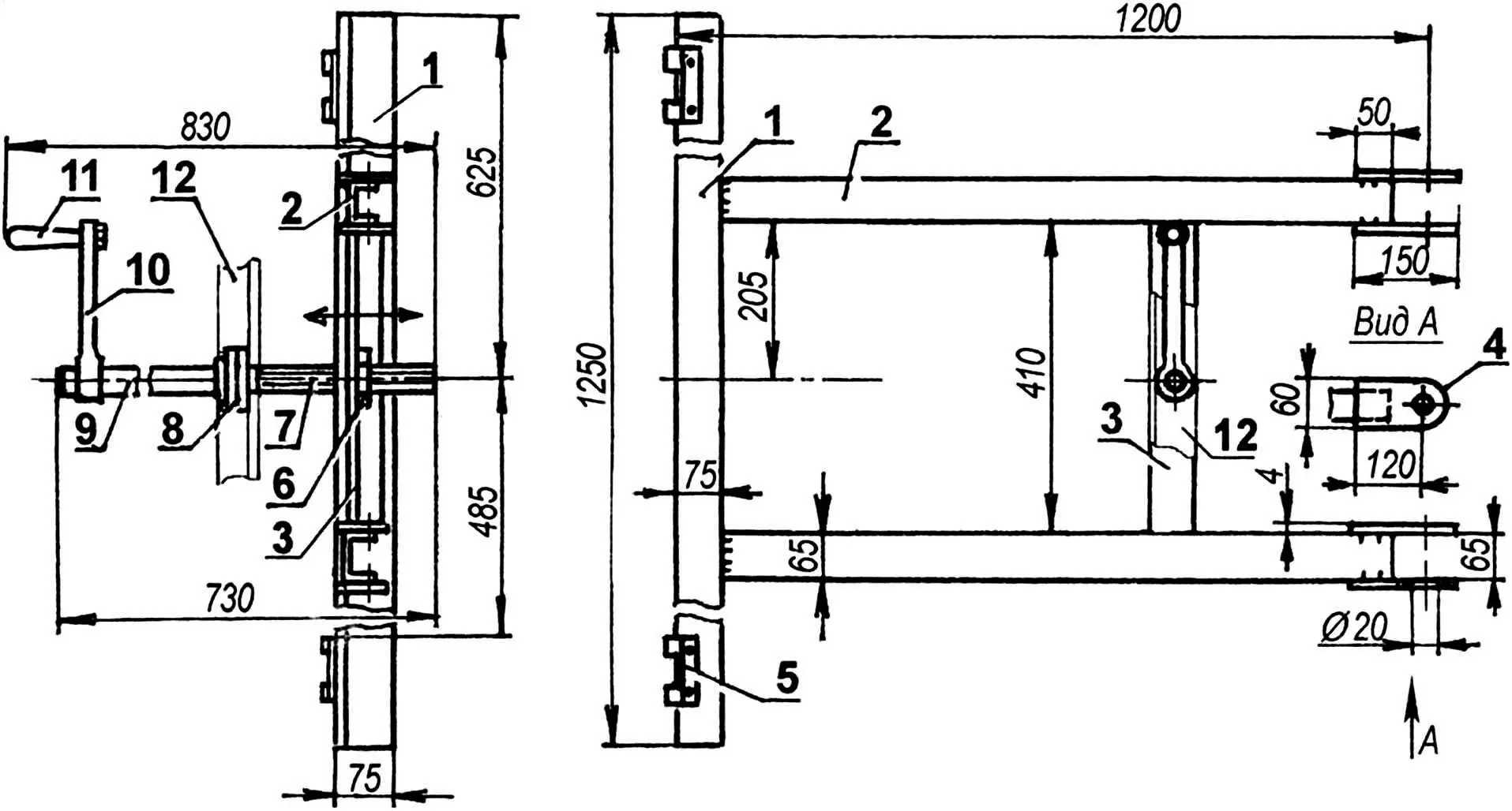
1 — cross member (angle 75×75); 2 — side member (channel 65×36, 2 pcs.); 3 — cross member (angle 36×36); 4 — eye (steel sheet s4, 4 pcs.); 5 — hinge loop card (second—mating card is attached to the mounted agricultural implement); 6 — nut (from bench vise); 7 — screw (from bench vise); 8 — thrust bearing; 9 — additional screw rod with welded thrust washer; 10 — handle lever; 11 — handle grip; 12 — frame diagonal tie
For connecting agricultural implements to the tractor, in addition to the drawbar, a hitch with a manual mechanical drive for raising and lowering implements is also made. The drive is a vertically installed screw jack. Its screw part, as well as the nut welded to the bottom of the hitch cross member, are used from large bench vises. Also on the right side of the frame in its middle part, a bracket is welded (not shown in the drawing) for attaching a modified and adapted former horse-drawn mower.
To hayfields, the tractor together with towed units is delivered in the cargo truck body. This is faster and safer than under its own power, and does not contradict traffic rules.
P. KUYANOV
Recommend to read
 IN THE WAKE OF THE “BIG BROTHER”
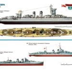
After the complete defeat in 1898 in the war with the United States, Spain, once a great naval power, retreated far back and fell into a deep "hibernation". Moral decline in society the... MORE ABOUT THE LAMPS
The era of universal shortage has prompted us to create the things in the shops it was impossible to find. However, the era of abundance has not stopped this process. Apparently, a...
