 (The end. Start at # 1’04)
Power bracket (Fig. 7) is welded in the form polukrovka of steel sheets of different thickness. At its rear side is located, as already mentioned, the hole for the adjusting screw and knurled nut mechanism vertical “guidance” of the pendulum and bracket mechanism of its fixation in inoperative position.
The front power mounting bracket has a committed console with curved end, a reinforced gussets. At the end of the — knurled nut, bushing which after the introduction into the hole flared to not fall out. The nut is coupled with the hinge bolt and the spring constitute the balancing mechanism of the pendulum.
Polukrovka in the bottom of the hole is provided with thread M 14×1,5 into which is screwed secondrun and nut threaded end of the vertical axis, designed to turn power bracket. Here is a circular scale with divisions of 3° — it measured the angle of this rotation.
To the rear polukrovka three screws M6 is mounted in the housing of the remote control of the machine, welded of sheet steel.
In the right side of the console alcove, protecting against mechanical damage the socket with indicator lamp, fuse holder, toggle the power and reverse the motor.
Frame Assembly (Fig. 9) is made of a rectangular cut of the pipe. Its front end is welded a transverse plate with various holes: a Central screw designed for mounting removable devices, six side — stepped adjustment of the position of an intermediate flange.


Fig. 15. Attachment for chain sharpening:
1 — knob with shaft; 2 — Teflon washer (s2); 3 — roller bearings; 4 — lead flange; 5 — spacer washer (sl, 3). 6 — led flange; 7,13 — compression springs; 8 — adjusting sleeve-nut M10; 9 — nut M10; 10 — pin (Ø3, L19,5); 11 — rod; 12 — wedge-sleeve; 14 — hook remover saw chains (steel, sheet s2); 15 clamp, holder hook (motorcycle); 16 — additional stock; 17 bolts M14; 18 — a primary shaft; 19 — washer spacer (s1, 2); 20 — finger; 21 — guide pulley; 22 — M12; 23 — the wedge-nut M12; 24 — rotary console
On the bench frame rests side legs and a rubber cushion and is held securely by screw clamp. In the base frame welded bushing with PTFE liner under a vertical axis of rotation of the power bracket. A predetermined position of the latter is fixed because the sleeve is equipped with a special wedge clamp for the axis.
The front frame is fastened to the intermediate flange. It has a threaded slot hole: the first under the screws swivel console console designed for sharpening saw chains, the speed screws adjust the position of the intermediate flange. The angle of the flange can be assessed in a limb with divisions 1.5° C, plotted on top of its edge.
The most common CCS tool is a grinding wheel (Fig. 10). In working condition it is securely covered with a protective casing (Fig. 11), lying with his neck on the left bearing housing of the working shaft, on the end of a pendulum, and attached to the flange of this enclosure with just one screw MB. In case of replacement of the abrasive wheel screw is easy to Unscrew, the casing on the swivel axis to tilt back until it reaches the motor and thus open a free access to the working shaft.
The cover has a rubber apron protects the control panel from bombing it with sawdust and particles of the abrasive wheel.
The clearance between the housing and the pendulum is installed on a combined electric lamp bracket (Fig. 8, 12). This place is the most comfortable: light, without dazzling the operator covers the treatment area.
Now some of the fixtures to the machine. The main of them — telescopic attachment for sharpening saw chains (Fig. 15). It is attached to the frame through the intermediate flange with two screws.
The console consists of a rotatable arm with a simple clamping device, a rod, upper and lower rods, springs and guide pulley. The most complex nodes — rod (Fig. 14), riveted from welded bracket, cylinder and liner, and steering console.
In addition, the console is supplemented with the holder (clamp from the handle bars) and hook that are required for donning and doffing saw chains (design of puller is shown in a separate figure).
Rod is welded from three parts: a horizontal sleeve, vertical Cup and the connecting wall.
In the horizontal sleeve are a kind of roller bearings (Fig. 15), consisting only of external clips (pipe segments) and a set of rollers. The inner diameter of the clips and diameter of rollers are designed so that the shaft with mounted on it the handle is rotated in the bearings.
Glass (also chiseled detail) designed to clamp in the bore of the rotatable arm, so he has such thick walls. The glass is fixed a thin-walled cylinder with klapannym it liner.
The limb on the rim of the glass allows you to set the rod (and hence the saw chain) at the desired sharpening angle.
On the smooth cylindrical section of the shaft with the handle, rotating in a roller bearing sleeve, wearing two friction flanges and their compressive spring.


Fig. 21. A set of tools for the dissolution of the lumber and grinding metalwork and woodworking cutting tools:
1 — rotary console; 2 — M8 bolt with a shaped head (2); 3 — rotary table; 4— angular flange; 5 — nut M8 (2 PCs); 6 — locking screw M5; 7 — the armrest; 8 — angle gauge; 9,22 — sharpened tools (drill bit and the plane piece of iron); 10 — spread timber; 11 —circular saw; 12 — shield; 13,20 — thumbscrews M8 (3 PCs.); 14 — Desk; 15 is a movable guide rail; 16 — axis of rotation of the desktop; 17 — screw M6 fixing desktop; 18 — the pendulum of the machine; 19 — locking винтМ8; 21 — the holder; 23 — vices
One of the flanges leading, as it is associated with shaft short pin that is pressed into a radial bore of the shaft (after the introduction of the latter in the bearings). Second, the driven flange is connected to the leading three of his spikes. The compression force of the spring is regulated by a sleeve-nut, the fixed nut.
The friction flanges named because the ridges worn for sharpening a cutting chain fall between them and are held due to the friction forces caused by the compression of the spring. Therefore, any rotation of the handle of the saw chain moves, exposing every tooth under the grinding wheel.
This simple solution allows you to efficiently sharpen the chain of different steps and to do without a whole set of additional removable stars.
Except the saw chain, different brands differ in length. But the exit is found here: the main stem of the prefix can be extended to 100 mm, using an additional rod and the connecting stud (tighten by hand).
Saw chain fits over the console and removed from it one and the same instrument — the special puller (Fig. 13). Describe his device is not necessary, because everything is clear from the figure.
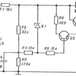
In a set of electrical equipment of the machine (the circuitry in Fig. 16) enter the engine type AVE-0,71-4C with junction box (Fig. 18) and control panel (Fig. 17).
On the right front panel of the remote control buttons START and STOP, and the left socket for additional devices of a power not exceeding 20 watts, powered by an alternating electric voltage of 12 V. since the remote is attached to the power bracket, then automatically repeats it with circular movements. Therefore, the access control buttons easy always.
Readers who want to reproduce the design of the proposed machine will surely appreciate his ability not only when sharpening saw chains, but in other transactions.
For example, another device, or rather a set of devices is designed for grinding of plumbing and carpentry tools, drill bits, cutters on wood and metal, and for metal cutting and processing of wood (Fig. 21).
The basis set rotary table with vertical axis, the turning insert in the console (when the console is removed for sharpening saw chains), in which two bolts with shaped heads are attached to different holders.
For example, for fixing treated wood and metal parts on the rotary table set Vice; and for sharpening tools — angular flange with T-shaped armrest which can be rotated to the desired angle to the vertical. On the armrest and placed either the sharpen tool, for example, the plane piece of iron (pressed against the armrest with a special holder with screws-lambs) or angle gauge with a groove in which to fit the drill.
Unfortunately, the power of the electric motor AVE-0,71-4C (180 watts) is not enough to handle the massive wooden parts. However, if you use motor type AOL-21-2 (400 W at 2,800 rpm), given that the engines AVE and AOL the shaft diameters, dimensions of locating pins and the distance between them is the same, the processing on the machine will cease to be problematic.
ATTENTION! For of risk of injury at the running nodes and details of the machine have no sharp edges and corners. With the same purpose, it is painted bright alkyd enamel PF-115. However, when the machine is recommended to strictly observe safety precautions and work only in goggles!
In conclusion, I will tell you from which borrowed some components and parts of the machine.
The motor, driving and driven pulleys from washing machines SMR-1.5 “snowflake”.
Coil spring tension used in the balancing mechanism of the pendulum from the hanging hood of the car ZIL-130.
As for consoles for sharpening saw chains, its shaft with a handle, is nothing like one of the screws securing the cover to the cylinder head of a diesel engine of KDM. The quick release clamp on the rod — part bracket handle bars.
Then all the details listed — charged marine diesel engine brands D6.
Primary and secondary stocks is a modified part of the intake valves; port pin — cut thread of the same plate valves; roller bearings elements of the fuel high-pressure pump.
V. PETROV, S. fish, Krasnoyarsk Krai


