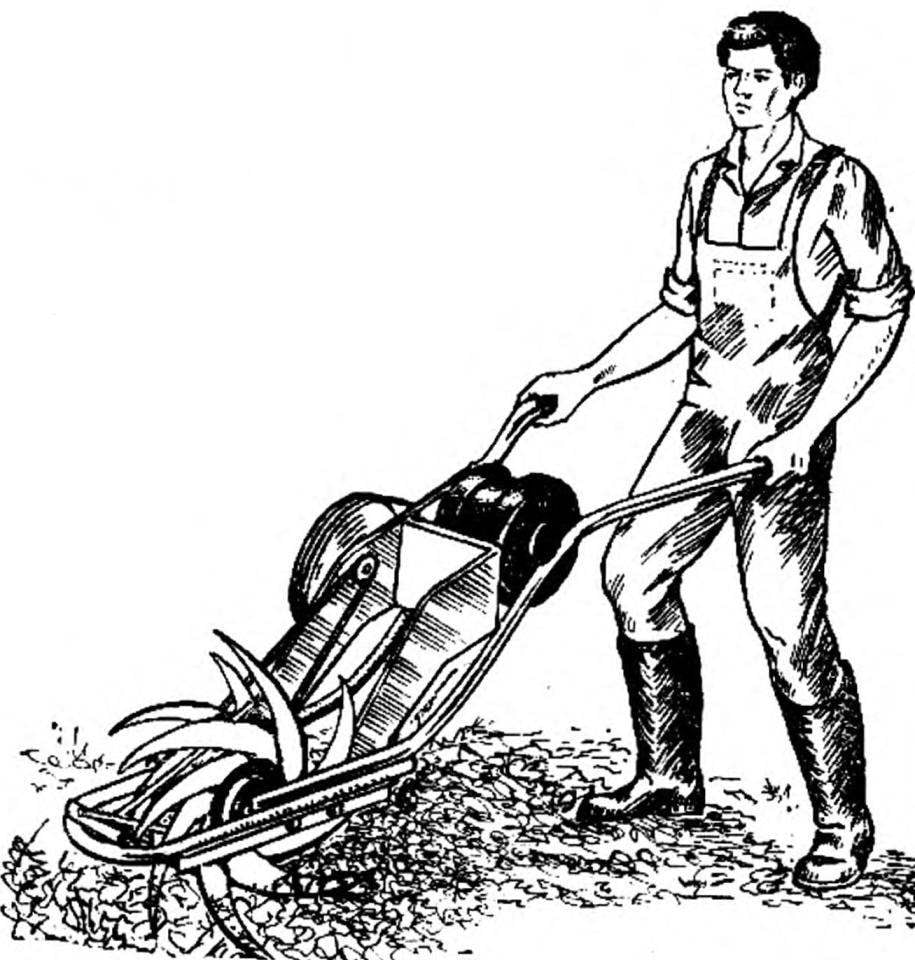
No doubt, the motor-plow or microtracker in the farm economy — assistant-all-trades. But where the plot-all small, and the garden trees and shrubs planted densely enough, the walk-behind combustion engine just to turn around. Here and come to the rescue of a simple, but very effective! the cultivator on the basis of the motor from the washing machine. Its working wheel with long narrow teeth perfectly reserves the loosened strip of land width of about 120 mm at a depth of pereopisanie to 150 mm.
And the overall layout of the design ensures the minimum width of the working unit (without handles) — 175 mm. this makes It easy to maneuver in mezhdureche, on narrow plots of land along the house, between the bushes — that is, where previously could be used only hand tools.
The main working body of the cultivator — steel drum Ø 200 mm, which is welded circumferentially narrow saber-like teeth. Wiring them all (like the teeth of circular saw blades) ensures uniform loosening of the soil across the width of the treated strip.
 No doubt, the motor-plow or microtracker in the farm economy — assistant-all-trades. But where the plot-all small, and the garden trees and shrubs planted densely enough, the walk-behind combustion engine just to turn around. Here and come to the rescue of a simple, but very effective! the cultivator on the basis of the motor from the washing machine. Its working wheel with long narrow teeth perfectly reserves the loosened strip of land width of about 120 mm at a depth of pereopisanie to 150 mm.