With the development of cooperatives in our country, the number of people wishing to apply their knowledge and skills in the agricultural sector, for example, in creating an apiary, raising rabbits or breeding poultry, is constantly growing. But enthusiasm alone is clearly not enough here – you also need to have the appropriate equipment, say, the same hives, cages, incubator. But the trouble is, buying ready-made equipment is sometimes very difficult, and often simply impossible. And then you have to do everything yourself.
For those who want to start raising chickens, we suggest building a semi-automatic incubator yourself.
Before you start building an incubator, determine how many eggs it should be designed for. With a capacity of up to 100 eggs, you can make both a simple and semi-automatic incubator; With a larger load, its design becomes more complicated.

1 — control unit, 2 — connector, 3 — cover, 4 — side wall, 5 — rear wall, 6 — door, 7 — viewing window, 8 — bottom, 9 — heater, 10 — tray, 11 — tray holder bar .
First, the number of eggs per set is determined. It should be said that chicken eggs can be placed in an incubator “conveyor” at intervals of 21, 7 or 3 days. This depends on your ability to collect the required number of fresh eggs for the next laying within seven days: with a longer accumulation period, the hatchability of chickens from over-exposed eggs decreases sharply. And for one laying with a period of 7 or 3 days, you need much less eggs.
With laying intervals of 21 days, the brood tray also serves as an incubation tray. For a seven-day cycle, there must be at least three incubation trays and one brood tray. For a three-day period, the number of incubation trays is set to six or more.
If you plan to breed turkey poults, ducklings or goslings, the full incubation period does not fit within these intervals. Therefore, the pauses between egg laying increase by 6, 7 or 9 days, respectively, until a brood appears in the first egg laying.
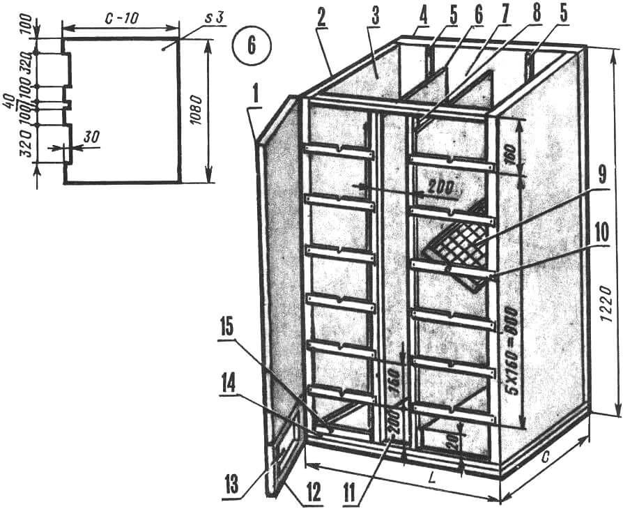
1 – top door, 2 – side wall, 3 – incubation chamber, 4 – rear wall, 5 – vertical bar for attaching trays, 6 – partition, 7 – ventilation cavity, 8 – vertical stand (block with a cross-section of 40X40 mm), 9 – incubation tray, 10 — tray holder bar, 11 — installation location thermostat, 12 — lower door, 13 — viewing window, 14 — bottom, 15 — brood tray.
We offer three versions of the incubator for self-production: a single-tray and two two-chamber incubators – a three-tier (six incubation and two brood trays) and a six-tier – for twelve incubation and two brood trays.
Depending on the need for chickens, you can choose an incubator with a capacity of from 15 to 1800 eggs, and their number per laying ranges from 15 to 300 eggs. Eggs are laid in a single-tray incubator with a period of 21 days; in a three-tier – with an interval of 7 days, if there are two trays, or at 3 days (one tray each); and in a six-tier one – at intervals of 3 days (2 trays each).
The inner walls of the incubation chambers, spaced at a distance of 180-200 mm from each other, form a ventilation cavity through which fresh air enters. The width of this cavity depends on the diameter of the fan impeller.
The trays are mounted on round spikes and can be rotated 90°. Brood trays are placed on bars above the bottom, into which water is poured to maintain the desired humidity in the chamber. In a single-chamber incubator, three heating elements connected in series are installed along the perimeter of the bottom; in a two-chamber one, two parallel-connected heaters are located at the bottom and in the middle of the ventilation cavity. At the top of the latter, a fan is installed with blades down for forced circulation of warm air in the chambers. Harmful gases are removed through holes in the lid.
The two-chamber incubator has four doors – two each for the incubation and brood sectors. The latter have transparent plexiglass installed to monitor the brood. The door of the single-tray incubator also has an observation window. The brood part is illuminated by an electric lamp.
Temperature sensors are installed in the left chamber above the top setter tray and below the brood tray; The electronic regulator is located at the front, at the bottom of the ventilation cavity. For a single-chamber incubator, the control device is located in a separate block.
| Option | Number of eggs in the tray, pcs. | Tray width, mm | Tray length, mm |
|---|---|---|---|
| 1 | 15 | 120 | 240 |
| 2 | 24 | 160 | 280 |
| 3 | 28 | 160 | 325 |
| 4 | 35 | 200 | 325 |
| 5 | 40 | 200 | 370 |
| 6 | 45 | 200 | 410 |
| 7 | 54 | 235 | 410 |
| 8 | 60 | 235 | 455 |
| 9 | 70 | 275 | 455 |
| 10 | 77 | 275 | 495 |
| 11 | 84 | 275 | 540 |
| 12 | 96 | 315 | 540 |
| 13 | 104 | 315 | 585 |
| 14 | 117 | 355 | 585 |
| 15 | 126 | 355 | 625 |
| 16 | 135 | 355 | 670 |
| 17 | 150 | 390 | 670 |
Using the table, determine the size of the tray depending on the number of eggs that you want to place on it. Then, based on the dimensions and number of trays, the structural elements of the incubator are calculated.
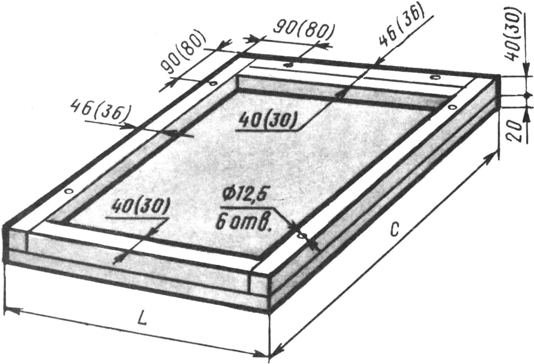
The bottom is made of boards or multilayer plywood, taking into account the thickness of the incubator walls and the width of the ventilation cavity. Blocks of section 36X30 and 30X30 mm (single-chamber version) or 46X40 and 40X40 mm (double-chamber version) are screwed to the base along its perimeter with screws. A series of through holes Ø12.5 mm are drilled into them for attaching the side walls. The inside of the bottom is coated with epoxy glue, and a plastic film is placed on top of it to form a waterproof trough.
The side walls are made of bars with a section of 40X40 or 30X30 mm and plywood 3 mm thick. The bars are fastened into a frame with screws; plywood is nailed to it on one side, and identical ones are drilled in a horizontal block opposite the holes in the bottom and rectangular M12 nuts made of metal plates are installed above them. The same holes with M12 nuts should be in one of the vertical bars – for fastening the rear wall.
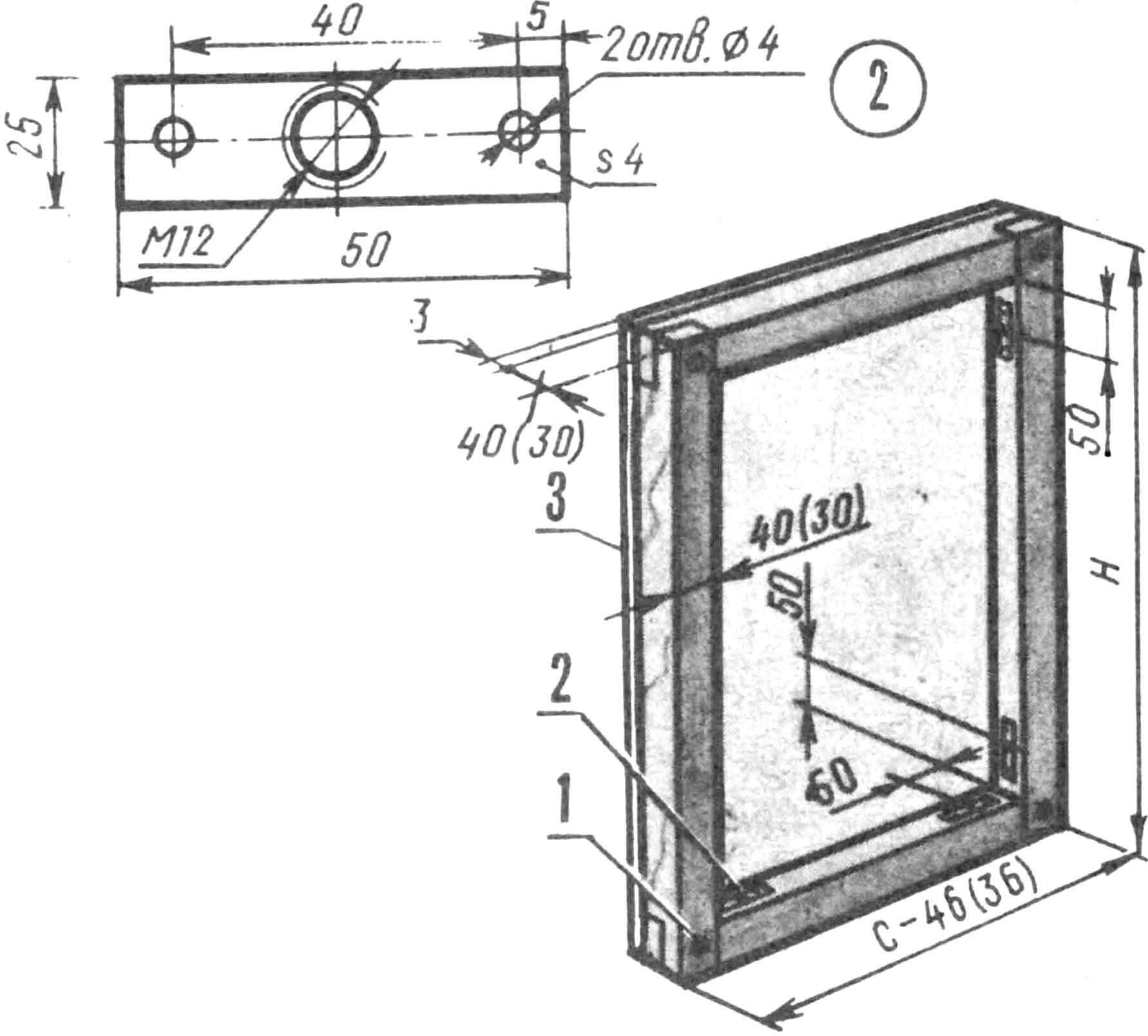
1 – screw 4X40 (30) mm, 2 – rectangular nut M12, 3 – plywood sheathing (the front plywood sheathing has been removed).
The back wall is made using the same technology as the side ones. Only in the center of the incubation chambers are two vertical strips with holes for the spikes of the trays attached.
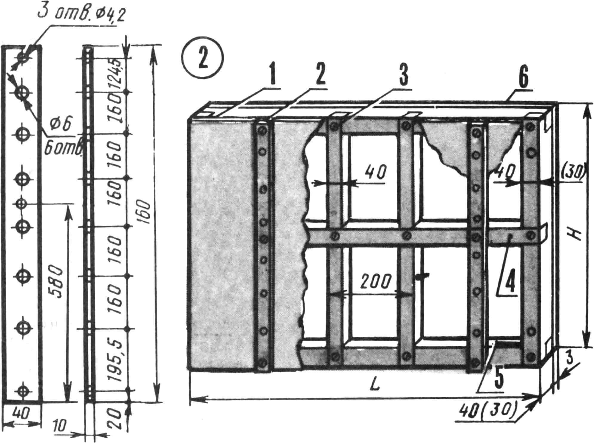
1 – screw 4X40 (30) mm, 2 – strip for fastening trays, 3 – vertical block (installed in a two-chamber incubator), 4 – horizontal block (only for a six-tier incubator), 5 – rectangular nut M12, 6 – plywood sheathing.
In a six-tier incubator, the rear wall in the middle part is additionally reinforced with a horizontal bar with a cross-section of 40X40 mm. Holes Ø12.5 mm are drilled in the bottom block on both sides and rectangular M12 nuts are installed to secure the rear wall to the bottom. The same holes are drilled in the right and left bars to fix the side walls. On the internal plywood sheathing, grooves measuring 100X3 mm are made for the corresponding protrusions on the partitions. The wall cavities are filled with foam plastic or other heat-insulating material.
The cover is made of multilayer plywood or chipboard in accordance with the dimensions of the bottom. You can slightly increase its width to form a canopy over the doors. In two-chamber incubators, for ease of servicing the devices, the lid is not fixed. Ventilation holes Ø10 mm are drilled across the entire surface in increments of 50 mm.
The doors are made as walls, using bars with a cross-section of 30X30 mm for two-chamber and 20X20 mm for single-tray incubators. The upper door closes the incubation part of the chamber to the axis of the lower tray. To ensure that the doors and lid fit tightly to the body, foam rubber is glued to them.
The partitions of the ventilation cavity are made of sheets of three-millimeter plywood: they are inserted at one end into the grooves of the rear wall, and at the other they are attached with screws to vertical bars with a cross-section of 40X40 mm, located in the front part of the incubator. Gaps of 60 mm are left near the lid and bottom.
Trays are made of steel with a thickness of 1 – 1.5 mm. A strip 60-70 mm wide is bent at a right angle on one side equal to 40 mm. The corners of the required length are butt welded.
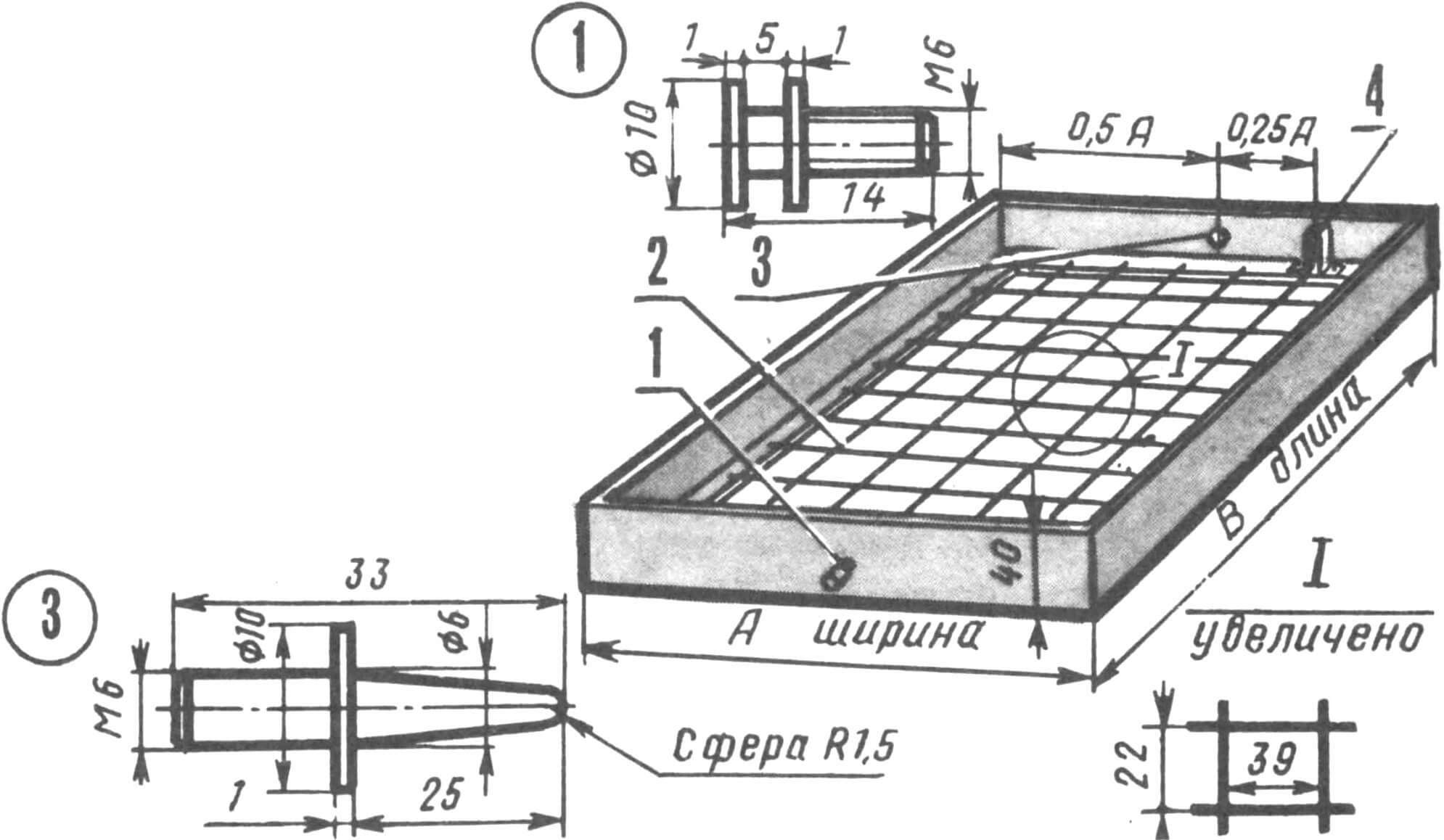
1 – front spike, 2 – wire Ø0.8-1.2mm, 3 – rear spike, 4 – protective casing.
The brood tray is covered from below with a fine mesh with cells of 1-2 mm, and between the opposite shelves of the walls of the incubation trays, wire Ø0.8-1.2 mm is pulled with such a pitch that a mesh with cells of 39X22 mm is formed. In this case, a stable position of the eggs is ensured.
In the center of the narrow end side, Ø6 mm holes are drilled to install the front and rear tenons. They are turned from metal on a lathe. On the back wall of the incubation trays, stepping back a quarter of its length from the right edge, another Ø7 mm hole is drilled for engagement with the rotating device rail. And in order to protect the eggs from damage by the spike of the rack, a protective casing is installed around the hole or a tube with an internal diameter of at least 6 mm and a length of 20 mm is rolled. The finished tray should not have distortions, sharp edges or other irregularities.
When all the parts are ready, begin assembling the body. M12 bolts are used to secure the walls to the bottom and to each other, then install partitions and front bars. Next, strips for trays are placed on the front of the incubator. Under them, using a chisel, make recesses in the side walls and front bars. Place the trays on the slats and check that they rotate freely.
The heaters are made of nichrome wire Ø0.4 mm, wound in increments of 0.5-1 mm onto a ceramic facing tile (preferably without glaze) measuring 75X150 mm. The spiral is covered with the same tiles on both sides, and asbestos at the seams. You can use other heaters with a power of 100-300 W.
In two-chamber incubators, the heaters are suspended on a wire in the lower and middle sections of the ventilation cavity, in the middle between the partitions. In the upper section, a fan is mounted on a bar. First, all “extra” parts are removed from it. The bar is installed in the recesses on rubber gaskets.

Then they begin to install the electrical equipment of the incubator.
Before assembling the incubator body, a device for rotating the trays is mounted on the rear wall, consisting of an electric motor at 30-60 rpm, a worm gear with a gear ratio of 40-80, a drum on the output shaft of the gearbox, four rollers and two nylon cords (Fig. 1) . The upper cord is secured to the drum with an M4 screw. The electric motor with gearbox is mounted on a separate chassis and fixed in the upper part of the rear wall with the drum facing up.
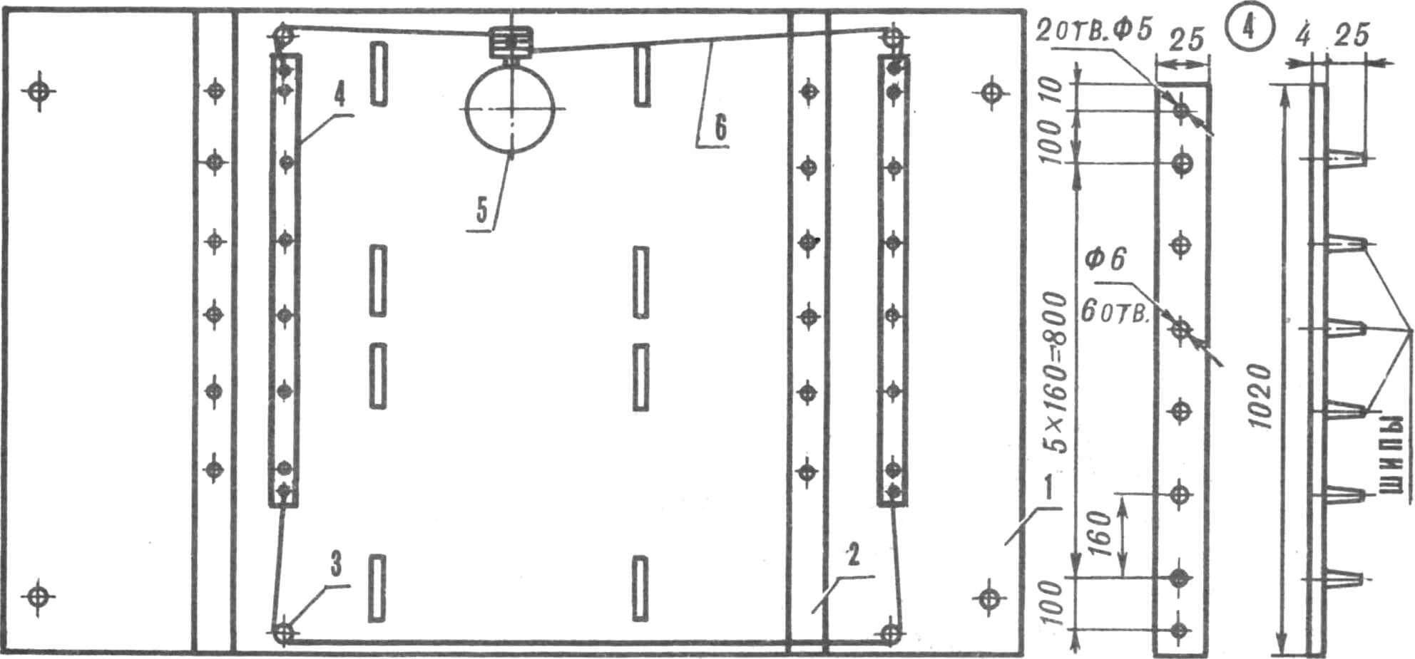
1 — rear wall of the incubator, 2 — bar for attaching trays, 3 — roller (4 pcs.), 4 — rail (2 pcs.), 5 — rotating mechanism, 6 — nylon cord (2 pcs.).
The rotating mechanism should ensure that the trays rotate through an angle of 90° in 10–30 s. Limit switches are installed on the upper front bar in such a way that when the trays are rotated 45° from the horizontal position, the upper tray presses the “limit switch” and turns off the electric motor.
Then they begin to assemble the incubator automation components – thermostat, thermometer, time relay, reversing device and installation of electrical equipment (connecting the power supply, heating elements, lighting lamps and temperature sensors).
The power transformer is located at the base of the ventilation cavity between the front bars. Temperature sensors are located above the top left setter and brood trays. Electric lamps (automobile 6-8 W, 12 V) are installed on the front vertical bars above the brood trays. Foil reflectors are placed on the light bulbs to protect the eyes from direct light rays.
The ventilation cavity is covered from the inside with 3 mm plywood. At the bottom there is a 40 mm wide slot for air outlet.
The two-chamber incubator is equipped with two thermostats, an electric thermometer, a time relay with a delay of 1 hour, a reversing device for the rotating mechanism and a power supply.
The thermostat consists of two comparators on microcircuits DA2, DA3 (Fig. 2), the inputs of which are included in the diagonal of bridges on resistors RK1, R4-R6 and RK2, R10-R12. Moreover, a thermistor RK1 or RK2—temperature sensor—is connected to one of the arms of each bridge. From the pulse shaper on MS DA1 and from the comparators, signals are sent to D-flip-flops DD1. Their outputs are loaded onto electronic relays VT1, VT2, which switch thyristors VS1, VS2, included in the diagonal of bridges on diodes VD6-VD9 and VD10-VD13, and through them the load – heaters R19, R20 and fan M1.
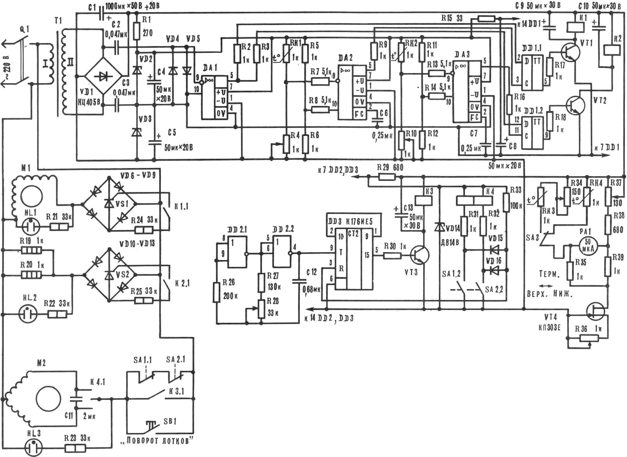
DA1 – DA3 K140UD1A, DD1 K155TM2, DD2 K176LE5, DD3 K176IE5; VT1 – VT3 KT603A; VD2, VD3 KS156A, VD4, VD5, VD15, VD16 KD503A, VD6 – VD13 KD202K; VS1, VS2 KU202N; HL1 – HL3 TN-0.3; K1 – K3 RES10 (passport RS4. 524.319).
The electric thermometer is assembled using a bridge circuit and is powered through a current stabilizer on a field-effect transistor VT4. Temperature sensors are thermistors RK3, RK4 brand KMT-4 or similar 1-1.5 kOhm. The temperature is adjusted using a variable resistor R37 located on the remote control.
The thermometer is adjusted using a standard mercury thermometer after the thermostat has been manufactured. To do this, the temperature sensors and the head of the mercury thermometer are combined together, eliminating the electrical connection of the sensor housings.
The thermostat is adjusted using a mercury thermometer to an operating temperature of 35° and with a variable resistor R37 the pointer of the PA1 device is moved to the beginning of the scale, calibrated to the interval 35° – 40°. Then the temperature is set to 40° and the variable resistor R36 in the current stabilizer circuit moves the arrow to the end of the scale. If the arrow “goes” to the left, then the polarity of the indicator head should be changed. The setup process is repeated several times.
To set up a thermometer with sensor RK3, set the temperature to 35°. Using the R34 regulator in the circuit of this sensor, move the instrument boom to the beginning of the scale, then check the correctness of the readings at 40°. If this cannot be achieved, the variable resistor R34 is connected in series with the sensor RK4 and the setting is repeated.
The time relay consists of a frequency generator of approximately 4.6 Hz on the DD2 chip and a divider by 32,768 (DD3), the output of which is loaded onto the transistor relay VT3.
Every hour, a high potential appears at the output of the divider, relay K3 turns on and closes the power circuit of the electric motor M2. He will turn the trays, and the limit switch will reset the counter-divider to 0. The power supply circuit of the electric motor will break, it will stop, and the polarized relay K4 will prepare M2 for reverse operation.
In a single-tray incubator there is one thermostat (Fig. 3), and it is easier to make the rotating mechanism continuous, driven by a time relay of the VS-10 type for 60-120 minutes, through a rocker mechanism.

DA1, DA2 K140UD1A; VD2, VD3 KS156A, VD4 – VD7 KD202K, VD8, VD9 KH503A (B); K1 RES10 (passport RS4.524.319).
First check the operation of all incubator components and adjust the thermometers. Please note that the change in the resistance of the thermistor in a narrow temperature range is small, so you need to adjust the thermometers directly in the incubator.
After switching the temperature sensors in a two-chamber incubator, you need to wait 1-2 minutes until the thermometer mode is established.
Then check the operation of the rotating mechanism. To do this, press the rotation button on the remote control, and when the upper tray moves away from the limit switch, it is released. The trays should turn 90° and stop as soon as the top tray presses the other “limit switch”.
Test the operation of the time relay for two to three days. Every hour the trays should move to the opposite position.
The sensors are placed in their places, the temperature is set: 38° at the top and 37° at the bottom – and for two days they monitor its stability, the period of rotation of the trays, water leakage from the bottom, and the reliability of the entire incubator as a whole. Eggs are laid in the following sequence. By pressing the “Rotate trays” button, set the trays horizontally and turn off the network toggle switch. Then remove the top tray from the incubator and, supporting it with the long side, place it obliquely (at an angle of 30°) on the table. The eggs are placed tightly with the sharp end down so that when turning they do not hit each other or the walls of the tray.
The tray must be completely filled. If there are not enough eggs, fill the free cells with paper or other material.
After laying, the trays are installed in the incubator, the network switch is turned on, the rotation of the trays is controlled, the heating and fan indicators are verified, and the doors are closed. After two hours the upper temperature is adjusted.
The next bookmark is made in the same way after 3 or 7 days. A new batch of eggs is placed at the top, and those in the incubator are moved from the left chamber to the right one to the section below, and from the right one to the left one. This is done to heat the eggs evenly.
After filling all the trays, when the first batch of eggs is in the incubator for 19 days, or four days after the sixth laying (with a three -day cycle), the eggs must be checked and put on a brood. To do this, the trays are installed horizontally and the lower garden with eggs is taken out. Then they are sorted on a ovoscope for three groups. Eggs with a living embryo (dark on the lumen) are placed in a brood tray, without embryos (transparent and clean) can be used to feed future chickens – they are still placed in the refrigerator. Collect eggs with dead germs separately.
After checking the eggs and installing in the incubator of the filled brood tray, an incubation trays are rearranged and the laying of a new batch of eggs.
After about 24 hours, the first brood appears. Periodically, every 4-6 hours take out dry chickens and shells. At the end of the brood, the remaining eggs must be checked again – among them there may be alive. In the meantime, the new brood is ready for the calculation.
The effect of incubation regimes on the brood of young animals can be found in the book by N.P. Tretyakov and G. S. Krok “Incubation with the basics of embryology”.
A. Kazakov, G. Angren, Uzbekistan

