Parts of the hull were welded with the electric arc from DC using peeled from the coating electrodes with a diameter of 4 mm. to Brew a discontinuous way I initially was difficult, until I, as they say, smell the metal and not practiced. In this way, the seam is like overlapping fish scales, and the structure of seam — like porous.
When the “Star” was ready, I installed it on the motor “the Whirlwind”. However, the trials revealed a number of shortcomings: poor longitudinal stability, the overlap of water through the transom in a sudden stop of the engine and so on.
Had to upgrade the boat. And a few times. She had side Boule, sub niche, and more. In short, the Motorboats of the project “Star” I have become a sort of laboratory, where he tested various technical solutions. Over time, taking into account the experience gained through the identification and elimination of shortcomings and there was a motor boat “Mirage”.
Why is it given this name? The fact that in certain lights on the river, especially in hot weather, painted bright paint on the hull of the boat at some distance from the observer visually merged pivot surface, becomes like a Ghost. That is to say, the technology STEPS in action.
Principal dimensions motor boats
Cutting main elements of the case (material —sheet steel 1.5 mm thick)
Layout boats:
1. nasal septum; 2 — nasal unit of buoyancy; 3-stem; 4 — towing device; 5 — bow-deck; 6 — fore trunk; 7 — fender; 8 — gate; 9— paddle; 10 — mid unit of buoyancy; 11 — feed unit of buoyancy; 12—transform the block of buoyancy; 13 — the bottom skin mountain niche after peak; 14,18,21,24 — floribert; 15 — soles; 16,19,23 — bottom the buoyancy blocks; 17 climbing the Bank; 20 — eptember slot with oarlocks and anchor-mooring duck; 22— removable Bank; 25 Kil; 26 — hinge (piano hinge); 27 — cover the bottom of the trunk; 28 — bottom of the trunk
Why the choice of the object for publication fell on the Mirage?
Immediately say, that in no case do not claim to exclusivity of this design. I just wanted to show what can be done with modest financial and technical capabilities of homebrew that guided the wise proverb, “patience and a little effort”.
“Mirage” had been chosen because he, in my opinion, the most simple shape and production technology compared to other options. As for the simplicity of the contours of the boat, it largely predetermined not so much by design, as the choice of materials. Steel, to put it mildly, this is not the best material to build boats. Steel large specific weight, poor corrosion resistance, especially in water, and many other disadvantages. However, steel is easily processed and that the most valuable, well welded using a normal arc.
What exactly represents a “Mirage”?
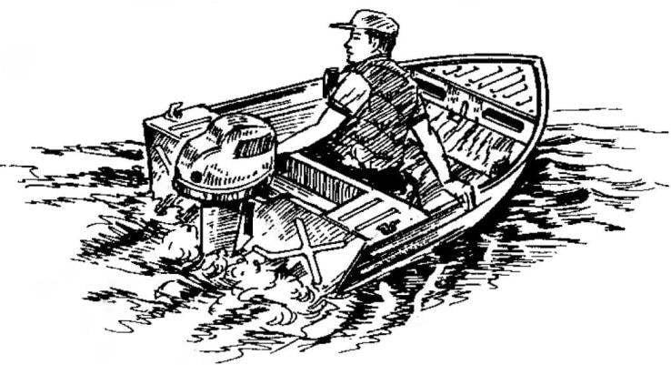
These small-sized, welded, to the carrier partially covering the boat with an outboard motor “Whirlwind” capacity 20 HP (14,7 kW). Developed its maximum speed with one person on Board — 48 km/h.
During water walking in a rather spacious cockpit of the motorboat can accommodate up to three people, if Amateur fishing — two. For these purposes, and created a “Mirage”. It does not have signal lights and remote engine control. Because of the low deadrise bottoms and other design features of the boat operation is not allowed when the wave height exceeding 30 cm.
In the forepeak of the body has dovolno roomy trunk, which is loaded through hatches cut in the forward bulkhead. (It should be noted that this bulkhead is not vertical, but tilted to the stern 2°.)
50 mm below the slices (edges) hatches in forepeak rigidly secured bow buoyancy block foam stamps PS-1. Unit before installing ollagen hot iron that made its surface smooth and durable. As the manholes have no covers, the items loaded in the trunk, are kept from falling out by excitement and shaking the boards with the height of 50 mm.
Power set housing (basic material sheet steel, 1.5 mm thick):
1 — stem; 2 — nasal septum; 3,4,5,6 — Fortenberry No. 1-4; 7—keel; 8 — eptember; 9 — 8 weld nut M6 (steel, sheet s3, 8 PCs); 10— power cnica (8 PCs.)
Stern sections (a — top view b — bottom view):
1,6 — anchor-mooring duck; 2 — aft deck; 3 — the left side of pulmotor Noi niches; 4 — left-hand safety bracket; 5 — the bottom of the sub niches; 7—through transom stringer: 8,13 — right and left transom stringers; 9,12 — drain water from under engine NSI; 10 — a screw-threaded plug hole to drain the water from the housing; 11 — trim plate for lock clamps of the outboard motor; 14— transom; 15,18 — mounting ears to the sides; 16 — left feed block buoyancy (right conventionally not shown); 17— M6 nuts attaching the right ducks; 19 — washer-lining right safety bracket; 20— the middle unit of buoyancy; 21 — backrest aft deck
Cross-section of the body (front view):
1,12 — side panels (steel, sheet s1,5); 2,11 —. toprimary (steel, sheet s1,5); 3,25 — zygomatic knize (steel, sheet s1,5); 4,9 — welded M6 nuts (steel, sheet s); 5,8 — bottom panel (steel, sheet s1,5); 6,7-Fortenberry (steel, sheet s1,5); 10,22— anchor-mooring ducks (steel, rod d8); 13 — screw-type lug (steel, sheet s2, 4 pieces); 14 — bolt М6х50; 15 — end (steel, strip 20×2); 16 — collar (pine, bar 40×20); 17 —fender (pine, bar 40×20); 18 — podshipnikoviy (PTFE); 19 — bearing oarlocks (steel, pipe 27×2); 20 — weld-on nut M8; 21 — locking screw M8; 23 — keel (steel, sheet s1,5); 24 — strip (steel, sheet s1,5)
In the cockpit on the twenty floriberto M6 screws with semicircular heads and slots it under the flat of a screwdriver fixed the soles of bakelizirovannoj plywood with a thickness of 7 mm. the Soles almost completely covers the bottom and has minimal clearance with the sides; in places of bilge brackets in it, made the appropriate cutouts.
Ahead, at a distance of 1300 mm from the nose, the soles ends. There he rojalnoj a loop attached sheet bakelizirovannoj plywood and cover the bottom of the trunk. Its free front edge, the center of which is carved grip for the hands, cover at an angle of 25° to the horizontal falls on the forward bulkhead and forms under another amount of Luggage. Thus, the bow of the trunk is used for light and afraid of water things, and the bottom, to roughly: ropes, salog, anchors and so on. And again. Even with our meagre summer sun and the rare calm weather on the soles you can relax and sunbathe: cover the bottom of the trunk serves as a comfortable headrest and a fairly high side of the boat to protect sunbathers from the wind.
Located under the soles are contoured on the bottom, the buoyancy blocks Styrofoam brand PHV-1. Sandwiched between the soles and bottom, these units together with the power set perceive themselves shock loads caused the hull with the waves.
The fore deck is made of steel sheet 1.5 mm thick. the Edge of the deck facing the cockpit, attached to the rounded form in order that when removing a motor boat on shore for this curve can be taken as the handles. On the remaining edges of the deck are made flanging, and on the surface, along the centerline of the stiffening elements in the form of punch — ridge.
Incidentally, the fore deck was mounted in the last turn — along with the ribs and RUB rails. And if specifically, first I painted the inner surface of the forebody, was placed in a pre-customized in shape and processed by hot iron bpoc buoyancy and then painted the bottom deck was set in place, gently taking her by electric welding to the sides at four points. After that, alternating in a checkerboard pattern screws size 4×40 mm, sealed their ribs and RUB rails. Under heads of screws along both ribs over the entire length of the hull planted fittings — steel strip section 20×2 mm. in addition, the ribs and RUB rails somewhere around the perimeter additionally pulled with ten M6 bolts.
Forepeak:
1 — weight; 2 — flange; 3 — fender; 4 — nasal septum; 5 — bow deck (steel, sheet s1,5); 6 — inner pad (steel, sheet s2); 7 — outer trim ring and towing eye (steel, sheet s2, the rod d8); 8,13 — side panels; 9,11—bottom panel; 10 —keel; 12 — plate splice (steel, strip 20×1,5)
Side knize on floriberto No. 1,3,4:
1 — partimers; 2 — the zygomatic major cnica (steel, sheet s1,5); 3 — side panel
The design of the after peak:
1 — screw plug М16х 1,5 (D16T); 2 — transom; 3 — panel (bakelite plywood is waterproof s7); 4,14 — transform the blocks of buoyancy (foam PS-1); 5 — left transom stringer (steel strip 40×4); 6 — through transom stringer (steel strip 40×4); 7 — the contribution from dysh (rubber Mat s8); 8 — transom Board (pine, boards, s40); 9 — bottom skin Torno niche (steel, sheet s1,5); 10 — left feed block buoyancy (foam PVC 1); 11 — left side plate sub niches (steel, sheet s1,5); 12 — median unit buoyancy (foam PS-1); 13,15 — sewing transom buoyancy blocks (steel, sheet s1,5); 16—aft deck (steel, sheet s1,5); 17,19 — washers (steel, sheet s2); 18 — left the safety clip (steel, rod d8); 20 — washer; 21 — o-ring (rubber); 22 — weld-nut M 16×1,5 (steel, sheet s7)
In the bow of the boat mounted towing device consisting of two angular plates of sheet steel, 2 mm thick, one of which (external) welded ring towing eye out of steel rod with a diameter of 8 mm. Mounting plates with clamped between the ribs privatename bars and flanging bow deck to the sides — place the four M6 bolts with a semicircular head.
Before optimisati I welded to the sides of the bracket for fastening a removable banks. Brackets, curved sheet of steel, have rubber bushings for metal Papiev, screwed in the corners of the seat banks. Thus, the shore, nature is easy to remove from the boat and put on shore. And when using a motor boat by one person removable Bank can never take with you, and take climbing to the Bank, made of Styrofoam brand PHV-1 and covered with fabric “Bologna”.
Around the circumference it has a loop of nylon cord with a diameter of 5 mm with handles and, if necessary, can serve as a rescue craft.
For the convenience of fishing rod there is a special fit — the holder of the rod with the possibility of adjustment of the rod both vertically and horizontally. The device is inserted into any of sockets rowlocks and lock screw.
The motor boat “Mirage” is equipped with two oars, made from dry spruce. After a full carpenter handling the oars were covered with two coats of hot linseed oil with required drying time between layers and painted with waterproof paint.
Oarlocks are made of steel forgings with subsequent metal processing and burnishing. In the holes of oars and rowlocks sockets pressed PTFE bushings of appropriate sizes.
For mooring and anchorages on the hull of the boat has four ducks: two on optimera, under the oarlocks, and two aft, employees are also sockets for the blades of the oars in the inoperative position.
The stiffness of the whole structure of a motor boat provided by the set of its power set (the keel with the stem, optimise, Fortenberry and zygomatic brackets), bow and stern decks, sub niche, ribs and RUB rails, as well as technological elements — ridges on flat surfaces, the keel, bilge and transom flanging welded seams.
Sub niche of the stern sections welded from separate panels. In the front corners of the niche built brackets for the carbine of the cable that protects the outboard motor from accidental loss.
Removable Bank (view below):
1 —emphasis (pine, Board 190×20); 2—finger mounting (4 PCs); 3 — seat (pine, Board 250×18); 4 — stiffener (pine, plank 100×10,2 PCs.)
The emphasis banks are removable (port side):
1 suspension bushing (rubber, s20); 2 — bracket (steel, sheet s2)
One of the four attachment points removable banks:
1 — seat 2 — M6 screws; 3 — bracket-blank; 4 — cushioning sleeve stop; 5 — finger mounting; 6 — cotter pin
Paddle (material — spruce):
1 — crank; 2 — spindle; 3 — blade
The node setup of the paddle:
1 — bolt M8; 2 — spring washer; 3 — paddle; 4 — spacer (PTFE, pipe 16×4, 2); 5 — bushing (Teflon, pipe 12×2); 6 — thole
Holder of the rod:
1—M8 bolt; 2—a flange of bracket (steel, sheet s5); 3 -bracket (steel, rod d8); 4 — locking knob with M8 nut; 5 — flange of the finger (steel, sheet s5); 6 – washer (GISTDA rubber, steel s5); 7 – finger (steel rod d12)
Bow towing device:
1 — inner cover plate (steel, sheet s2); 2 — external plate (steel, sheet s2); 3 — ring (steel, rod d8); 4 — the eye (steel, rod d8)
Anchor-mooring duck:
1 — legs (steel, rod d8); 2 — the base (steel, sheet s4)
Improvised equipment to punch ridge:
1 — hammer-odbojka; 2 —treated steel sheet; 3 — fasteners (nails); 4 — lodgements (steel, angle 50x50x5); 5 — longitudinal logs (pine, timber 180×180); 6 — transverse lag (pine, 180х 180, 2 PC.)
The technology of welding steel sheets butt:
1,2 — welded plates; 3 — plate splice (steel, strip 20x 1,5); 4 – lining (copper, strip 60×10)
Special tool for forming the flare from the leaf parts of the hull of a motor boat
Assembly bench:
1 — pile flooring (pine, boards, s40); 2 — circuit Board a motor boat; 3 — stops-limiters (nails); 4 — keel; 5 — after peak; 6 — wedge (pine, timber 50×50, 2); 7 — lag (pine, timber 180×100, 5 PCs); 8 — goats (3 pieces); 9 — cradle (pine, boards, s40); 10 — lock of the stem (pine, timber 180х 100)
Front under engine transom Board flush embedded rubber liner under plate clamp motor mounting and the rear panel is made of bakelizirovannoj plywood with a thickness of 7 mm. Between this package insert, transom Board and the cover are connected with screws and through bolts M6.
To drain the water out of the hull at the transom there is a hole with a threaded dural tube and seal rubber ring.
In addition, after peak as the most loaded part of the hull, is provided with a plurality of blocks of buoyancy. In particular, one middle (Styrofoam brand R-1) between the backrest of the aft deck and the front sub niches; two three-dimensional feed (Styrofoam brand PHV-1) — between the sides and the side walls of the sub niches; finally, two small transom (foam PS-1) between salutami these blocks, and transom.
Now I would like to elaborate on the technological features of Assembly of the hull of a motor boat.
The main feature is that first on the slipway using electric was going to the case bottom and side panels and the longitudinal power set (of the keel with the stem), and then it was mounted transverse power set. All parts of this set (fortenbery, toprimary and zygomatic cnici) were manufactured according to the dimensions taken from the hull place, so the exact dimensions in the figures are not given.
The second technological feature was the fact that the steel sheets are available at my disposal, not allowed to carve out a bottom and side panels entirely. Had to lengthen them back to back, using the lining material (steel strip section 20×1,5 mm) welded seams. Welding with a gap of 1 mm between the leaves was carried out on a smooth copper lining, which excluded the possibility of burning metal.
The contours of the bottom and side panels and the keel and stem were applied to steel sheets by means of special templates. The latter carve out a grid in full size of thin fibreboard.
Further the sequence of manufacturing these items will show on the example of one side panel.
With a sharp Scriber I moved from the template sheet outline panel (it includes future flare to weld on the hem). Relative to the zygomatic line marked the location of the ridges. (To punch these stiffeners I pre-made a special device and a hammer-podboju.) Squeezed in ridges as accurately as possible, with a small hood metal in a single pass over the entire length of the ridge. Such simple at first glance, the work required patience and skill.
Technology point of tack welding:
flanging of the panels is compressed ticks and ia this place electrode is applied to the welding point
Stage of welding work for assembling the housing of a motor boat:
a — dot potholder bottom panels to the keel and stern sections; b — point tack side panels; full welding of bottom and side panels solid seams; g-full welding of the side panels and aft deck;
Mykolaiv both zig, I turned over the sheet and strikes a wooden mallet to terms on a flat surface. Then electric as accurately as possible by marking the cut out side panel. It should be noted that in pairs folded along the side (and bottom) panel had to exactly match the contour. A clear mismatch was me. Otherwise, would be disrupted symmetry of the housing and complicated the Assembly.
A specially made tool I did flare at zygomatic line at an angle of approximately 45° in the direction of the hump ridge all the bottom and side panels.
Further, collected after peak, cook all the transom parts and sub niche in one. Then welded the keel of knezevo angle to the afterpeak.
Final Assembly of the unit was carried out on the slipway — smooth boardwalk with goats. Flooring boards were whitewashed with lime for fire safety, and then they applied the required markings in the form of axial lines and contours of the boards.
On the frame I installed the inverted stern sections with welded thereto keel, focusing on the axial line and secured. Giving bottom and side panels of the required curvature of hands of the blue beam, alternately grabbed them by electric welding. At the same time use steel strips with a cross-section 10×1,5 mm, putting them between the flare bottom, side panels and the transom (increase the thickness and strength of the welds), as well as a carpenter pincers, squeezing them welded areas.
Then finally welded body, applying a constant welding current of reverse polarity, is chosen empirically in the range of 25-90, and the electrodes with a diameter of 2 to 4 mm.
Pay attention to the fact that all of the long welds on the outside of the housing. External seams much easier to cook, and their quality becomes quite high.
When the joints have cooled, the boat turned, spaced location of the elements of the power set and the set of these elements, taking their points of welding. We did not forget to control a piece of wood laid across the sides, the geometry of the hull relative to the horizontal top of the transom. After all, even with very precise Assembly operations possible error of small curvature and thermal warping.
After welding I carefully cleaned all the seams with a wire brush, degreased with gasoline, primed and painted all surfaces. And after final Assembly, setting the buoyancy blocks, ribs and RUB rails, finally painted the hull motor boat with a waterproof enamel paint.
V. PETROV, Krasnoyarsk Krai
Recommend to read “ODNOTONNYMI” VITO: VAN AND BUS In 1995, at the presentation of the family Mercedes-Benz SPRINTER representatives of the company announced that it starts an active attack on the European market with their trucks.... AND WILL LOOP HIDDEN Offer homebrew. engaged in the manufacture or have manufactured furniture with doors mounted on piano hinges to replace them on domestic furniture, because the presence of piano hinges,...
Scroll back to top
 At the time I had a chance to build and test many motor boats. The first water I came off the boat “star”, the drawings of which were published in the October issue of the journal “modelist-Konstruktor” for 1966. It is known that the village of homebrew not spoiled by the wide range of structural materials. What was required for the construction of the “Stars” for a long time was not. Had to make do with what was in the moment at hand, namely, a steel sheet with a thickness of 1.8 mm. Naturally, the power set of metal profiles and strips of different cross sections, coupled with sigouney paneling gave the boat a pretty solid mass.