A growing number of adherents of the electric drive in our country. More than just attract them the most affordable to manufacture and easy to operate kordovye models with external power supply. Today created a lot of these models — among them kordovye “school”, kordovye “pilotage” and even kordovye speed. Of course, the most popular among modelers are elektroperedachi. This is understandable — the high power and small dimensions of modern motors make it possible to create models capable of performing practically the whole range of Pinotage.
In the journal “modelist-Konstruktor” No. 6 for the year 2002 have already talked about cord aerobatic model with a pair of electric motors type DK-5-19 is not too large power. Her flights have shown that the use of a twin-engine scheme was given not only a doubling of capacity of the power plant and, accordingly, increase the speed of the model, allowing to fly on cords of greater length. Importantly, this significantly changed the aerodynamics of elektroperedachi — improved airflow of the wing and flaps, which increased lift at low speeds and airflow stabilizer, which had a favourable impact on the manoeuvring qualities of the model.
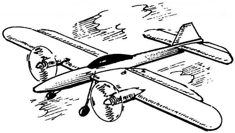
The promise of the chosen scheme encouraged to develop on its basis a new, improved version of the twin-engine model, the design of which already does not have the drawbacks and flaws that are inevitably there in the first version of flight spectrolite.
Twin-engine aerobatic control line model with electric drive and external power supply
Fuselage:
1 — the fairing nose (balsa); 2,17— stringers (Linden, rail 2×2); 3,13 — side walls of the fuselage (balsa plate s1,5); 4Д8 — the lower wall of the fuselage (balsa plate s1,5); 5 — panel (Linden, plate s4); 6 — frame No. 1 (balsa, plate s2); 7 — upper wall (balsa plate s1,5); 8 — a lining of lodgement of the wing (balsa plate s1,5); 9 — frame # 2 (balsa, plate s2); 10 — boss (Linden, plate s10); 11 — nut M3; 12 — frame No. 3 (balsa, plate s2); 14 — frame № 4 (balsa, plate s2); 15 — frame № 5 (balsa, plate s2); 16 — keel (balsa plate s3)
First of all, was the improved aerodynamics of the model: the midsection of the fuselage was reduced, the wing received the elliptical ending, which increase its aerodynamic efficiency, and new flaps. Elevators and flaps seleblitie made that simplified the design. Was upgraded and the motors for them are selected of miniature ball bearings and the new graphite .brush header, as well as improved cooling of the armature due to the large Windows in the front and rear walls of the engine. All this has allowed to bring to the motors high voltage and, as consequence, increase their capacity and frequency of rotation of the propellers.
Another design discovery that significantly improve handling properties of the model. As you know, when flying cord “trains” a small mass with a low-powered powerplant (of course, compared with internal combustion engines!) this files most often not provided the necessary tension cord that does not allow the model to perform spectacular maneuvers in the upper hemisphere. Once in the journal “modelist-Konstruktor” in one of the articles known modelers master of sports V. Tikhomirov proposed a simple way to increase the tension cord through the installation of vertically oriented aerodynamic surface, features resembling the keel of a yacht — the force by which it was directed “out of the circle”, which allowed to confidently pilot the model in the upper hemisphere even at relatively low speeds. The only “but” to equip such a “keel” a model is almost impossible— this resulted in too much rework. And addition, to be honest, not decorated model.
The proposed method of increasing the tensioning cord to install on an outer wing model of a propeller-rotor, as it is shown on one of the drawings. When flying pilotazhki rotor installed at a slight angle to the direction of the airflow begins to automotivate. In fact, the system began to resemble flying on the side of the gyroplane. Aerodynamic force due to autorotation of the rotor and directed “circle” sufficiently increases the tension of the cord. A propeller made of clear Plexiglas, the rotation is not visible and its presence in the model does not affect the visual perception of flying.
Horizontal tail:
1 —pylon rudder (aluminum, sheet s1); 2 — Central insert (balsa plate z); 3 — tor-Sion (steel, wire EOD d1); 4 — the Elevator (balsa plate s); 5 — struts (balsa rail 3×2); 6 — front flange (lime, rake 3×4); 7 — rear flange (Linden, rail 3×3); 8 — loop (nylon webbing); 9 — ending (plywood balsa plates s1,5)
Wing:
1 — ending (Linden, switching from two layers of veneer s1); 2— end rib (Linden, plate s2); 3 — flaps (balsa, plate s2); 4 — loop (nylon webbing); 5—torsion (steel, wire EOD d1); 6 — horn control flap (duralumin, sheet s1); 7 — rib (balsa, plate s2); 8 rocking of the control system (glass fiber, sheet s3); 9 — the leading edge of the wing (pine, battens 3×3); 10 — beam flange (pine, battens 2×5); 11,12—sewing Central part of the wing and mounting of the nacelle engines (balsa, plate s1); 13—rear edge of the wing (balsa rail 5×10); 14—wall boxes wooden (pine, rake 3×5);
Table coordinates of the airfoil (the Yak-55 -16%)
So, the cord electromilitary. The model is designed according to the scheme of the low wing with a symmetric profile. Design made using balsa, basswood and pine.
The fuselage model is made up of four walls (the balsa plate thickness of 1.5 mm) and six ribs (2 mm balsa plate). The joints of the lower wall with side strengthened by stringers — fake reek a cross section of 2×2 mm.
Purely technically the fuselage it is advisable to assemble as if there’s no groove under the wing in the area between the second and third frames. Cut it after curing the epoxy adhesive; then, before the third frame should be fixed fake boss taped it nut with M3 thread (it screwed the screws fastening the wing to the fuselage), then the balsa strip 1.5 mm thick to turn over the cradle of the wing.
The front wing fixed to the fuselage using 5-mm beech pin — when docking it is inserted into the opening in the lime fingerboard, glued before the second bulkhead of the fuselage.
Visseren glued the fuselage is covered and painted nitrogenatom autosmal. Lantern “pilot” stamped from blanks cut from the wall of a plastic bottle bluish color.
Fixed keel, cut from 3 mm balsa plate and tightly sealed in the rear fuselage. The front fairing of the bow is carved from balsa.
Horizontal tail inlaid design of glued balsa and fake pieces. Assembly of the stabilizer produced on-Board the stocks. Glued sterilizer visseren, profiled and covered with a thin colored Mylar film on glue BF-6. The elevators are cut from balsa plates on the stabilizer they are hinged, made of nylon braid.
Wing elektroperedachi stacked, cladding made from colored Mylar film. Wing profile is symmetrical, Yak-55 (modified with thickened trailing edge) with a relative thickness of 16% — this is more suitable for aerobatic models, because it has good bearing properties and provides a soft and smooth nature of the stall that will simplify piloting.
The wing is assembled according to the classic model of technology — on the Board-the staple was fixed protected by plastic film sheet of drawing paper with a planned projection of the wing and along the leading and trailing edges has two smooth rods. First on the stocks with pegs and pins was recorded and the front and rear edges of the wing and the bottom shelf of the spar, then balsa-tions of the rib, after which the joints were filled with slightly diluted acetone epoxy glue.
The next stage of Assembly — install the top shelf of the spar and zalivok of 1 mm balsa megstu the ribs at the junction of the wing and fuselage and the wing and engine nacelles. At the end of the frame right console fixed lead weight with a mass of about 15 g.
Rocking control cut from lightweight and durable insulation material glass fiber thickness 3 mm. Rocking chair installed in the box, glued the fake slats, and that— in a niche between the spars, between the first and second ribs.
Motors DC-5-19 modified — increased the window cooling, installed miniature ball bearings and graphite brushes. On the model the motors are connected in parallel and connected to the conductive Kardam using stranded wires 0,25 mm2 using soldering.
A fully prepared wing is covered with a thin colored Mylar film on glue BF-6.
Propellers with a diameter of 150 mm at a step of 150 mm carved from lightweight Linden-type standard plastic screws used on high-speed cord models. In principle, models can use the motors rotating in one direction, but to pilotage more profitable propeller installation with counter-rotating propellers, in which the gyroscopic moment mutually destroyed, which improves its maneuverability. However, the air screws should be mirror-symmetric.
Powerplant Cordoba elektroleta:
1 — spinner (polystyrene); 2 — propeller d150, h = 150 (light lime, rake 6×20); 3 — motor DC-5-19; 4 — nacelle (Vileika of fiberglass and epoxy resin); 5—wing
Device for increasing the tension of the cord:
1 — external wing of the model; 2 — bracket (made of anodized aluminum, sheet s 1); 3 — blade (acrylic); 4 — the hinge of the blade (steel, wire d1); 5 — the Central bushing (PTFE); 6 — axis screw (bolt with two nuts); 7 — bolt
Power is supplied from two electric motors connected in series motorcycle 12-volt battery, located in a small school backpack. On the control handle model at the top of the installed switch to start the engine. The battery pack is connected via a two-wire cord and connector and through the switch to live Kardam.
Lapping propellers has been reduced to the pruning blades with a test propeller systems models after each operation. To measure the magnitude of the thrust model is suspended on rubber thread propellers down. Going to serially right and left engines, estimated the magnitude of thrust of each of them. After final finishing, the screws were balanced and varnished.
A few words about the design of the screw-rotor serving to increase the tension cord. It consists of a Central hub, made of Teflon, and a pair of blades made of transparent Plexiglas. Blades fixed to the hub by means of hinges, which are to occur on the rotor heeling moment is not applied to the design model. The rotor is pivotally mounted on the bracket sheet duralumin, and that is at the tip of the outer wing so that the rotor axis was inclined from the axis of the wing spar at an angle of 5 degrees. When installing the rotor on the model of bracket is first fixed by only one screw, the second was installed after the test flights, which were chosen for the optimal installation angle of the rotor. Properly installed the screw-rotor during flight of elektroperedachi actively authorative, and at the same time significantly increases the tension on the cord.
I. SOROKIN
Recommend to read SLED WITH A PROPELLER This town is located in the Perm region. Called Tchaikovsky. In summer lives of ordinary working life. With the onset of winter is starting to sound a special music. It does not arise... INSTEAD OF A MICROPHONE — DYNAMIC HEAD When there are dynamic microphone, you can substitute any small-sized dynamic head. Here's what proposes to make to the Yugoslav magazine "Radio Amater". Since the voltage developed by...
Scroll back to top

 Specialized in aeromodelling magazines increasingly published articles about the model aircraft with electric. Today betrothe quite successfully fly and kordovye, and Svobodnaya, and RC models. The reasons are many, and one of the main can rightly be considered the appearance on the market of light and powerful power sources and motors, a compact and lightweight remote control equipment.