Six years ago I received land for a garden plot, and the problem of watering immediately arose. Pumping water manually is difficult and unproductive, and the gasoline engine does not seduce you with its noise and smoke, and you won’t have much trouble with it – carry it, secure it, remove it and take it away again. Therefore, the choice fell on a wind turbine. Moreover, the most ancient scheme – impeller, stabilizer, power take-off shaft.
The impeller drives the pump piston through an angular gearbox and a crank mechanism. You can, of course, do without an angular gearbox by placing a crank on the impeller and using the translational motion of a long connecting rod to drive the pump, but it is much more promising to use rotational energy for a variety of purposes. For example, if you put another gearbox below, you get a powerful winch, with its help you can uproot stumps, roots and even plow.
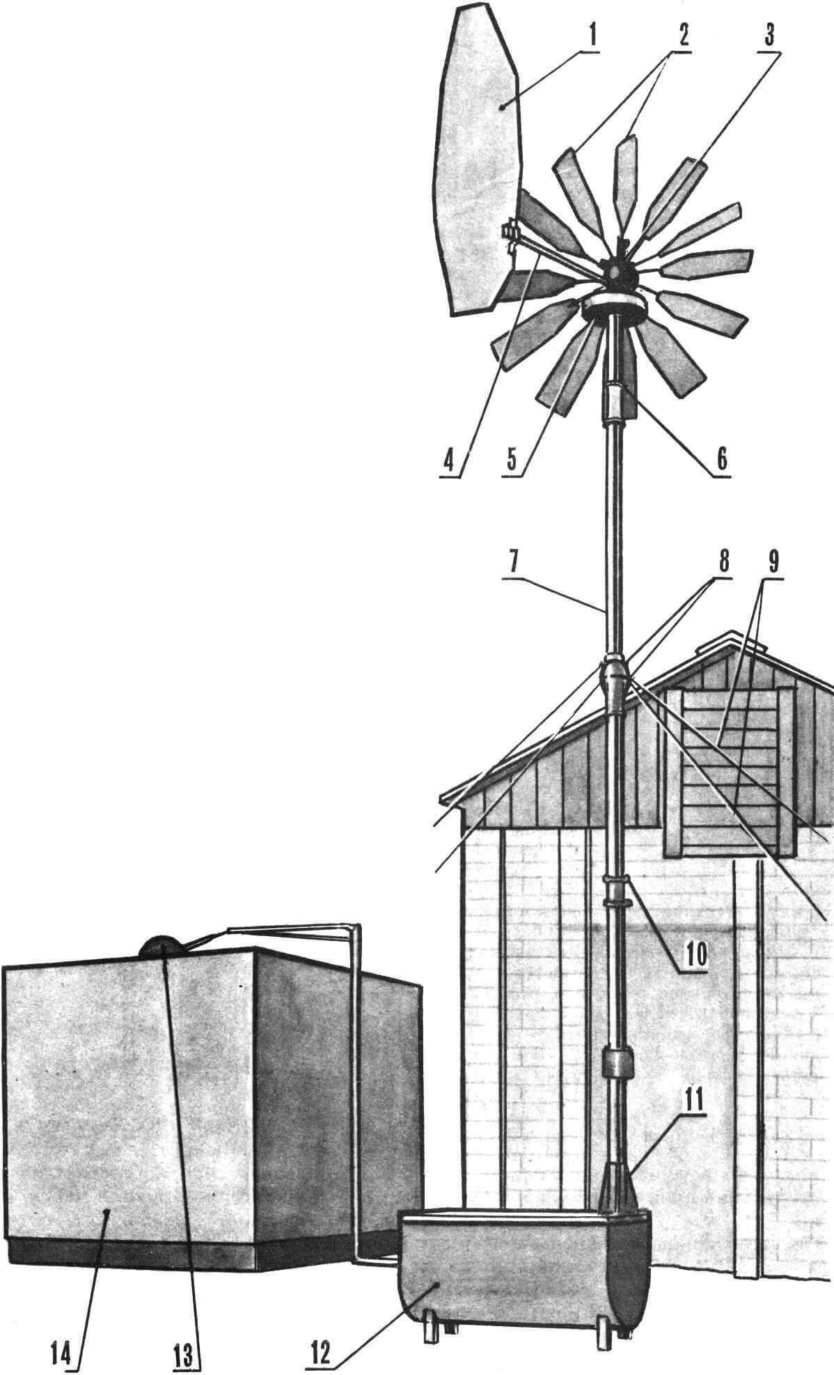
Pic. 1. Wind turbine assembly:
1 – stabilizer, 2 – blades, 3 – bevel gear, 4 – pipe, 5 – brake pressure washer in the casing, 6 – ring with shock absorber, 7 – mast, 8 – connecting flanges, 9 – braces, 10 – brake release device, 11 — mast base, 12 — box with pumps, 13 — float, 14 – container with water.
The simplest windmill, of course, is a rotary one, but compared to a bladed one under the same conditions, it is clearly inferior in power, so preference was given to the second one. With a relatively small size and weight, it has quite good parameters: it pumps up a container with a volume of 3 m 3 in a few hours in an average wind, and in an hour and a half in a strong wind. By changing the radii of the cranks, you can force the windmill to pump water even in light winds, although with less productivity.
My wind turbine works “orphaned”, that is, it waters the garden and turns off on its own. For irrigation in this mode, a drainage pipe connected to the irrigation pipeline is installed in the container near the maximum water level. Water that flows moderately into the container goes through the drainage into the system and is poured through a portable long pipe with numerous holes onto the area intended for irrigation where a lot of water is needed, for example, strawberries or raspberries. If the wind increases and the flow of water is greater than it goes into the irrigation system, then the rising level in the tank will change the position of the float, which, through the draft, will turn on the braking device of the impeller and it will stop. To turn the windmill back on, you need to lower the water level in the tank and move the brake release lever to the “Off” position. And in cases where there is no wind (although this rarely happens in our area), a hand pump connected in series with the wind turbine pump will help out; but basically it is needed only so that water can be pumped up for domestic needs at any time.
Operation of the wind turbine for five years has shown its advantages over other systems that consume any energy, especially gasoline ones. Firstly, this is primarily safety, secondly, autonomy and independence of energy sources, thirdly, constant maintenance is not required, and, last but not least, the windmill is environmentally friendly. In addition, this unique design will decorate the garden area.
The wind turbine consists of a wind wheel with a braking device, an angular gearbox, a stabilizer, a mast, a box with pumps and a windmill brake drive system connected to a water tank float.
The impeller is assembled from twelve blades made of hard duralumin 1 mm thick, riveted onto supporting spokes made of stainless steel tubes Ø 12 mm. For strength, Ø 10 mm tubes, also made of stainless steel, are driven into the supporting spokes from the hub side to a length of 200 mm. The supporting spokes are inserted into the guide sockets of the collapsible hub and clamped with bolts. The sockets of the supporting spokes are processed with a cylindrical cutter clamped into the chuck of a lathe.
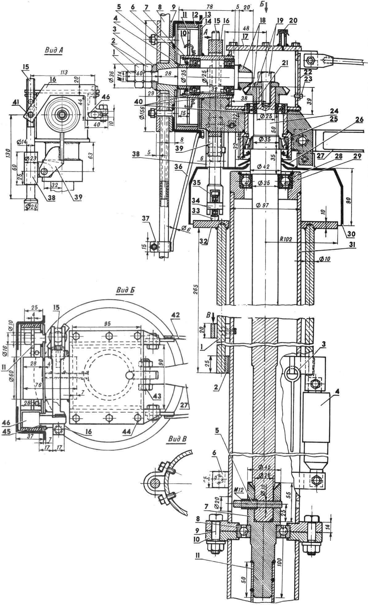
1 – horizontal shaft, 2 – M14 nuts, 3 – washer, 4 – spacer, 5 – M8 bolt, 6 – retaining ring, 7 – oil seal, 8 – blade spoke, 9 – hub, 10 – brake pad spring, 11 – brake block, 12 — friction lining, 13 — brake drum, 14 — brake drum guard, 15 — rod, 16 — lever, 17 — gear housing, 18 — gears, 19 — M12 bolt with washer, 20 — breather, 21 — key, 22 — manhole cover, 23 — M4 bolt, 24 — vertical shaft , 25 — bearing No. 2007107, 26 — rubber gasket, 27 — stabilizer pipe, 28 — bearing No. 80207, 29 — support sleeve, 30 — casing, 31 — mast, 32 — pressure washer, 33 — bandage, 34 — pin, 35 — bearing No. 80201, 36 — thrust spoke, 37 – clamp, 38 – guide bushing, 39 – bracket, 40 – bearings No. 205, 41 – support pin, 42 – stabilizer extensions, 43 – M10 bolt, 44 – M6 bolt, 45 – bushing, 46 – expansion cam.
Pic. 3. The upper part of the mast with the brake system drive:
1 — pressure washer rods, 2 — movable ring, 3 — brake system release rod, 4 — shock absorber, 5 — locking pin, 6 — support clamp, 7 — turned shaft shank, 8 — bearing No. 307, 9 — M12 bolt, 10 – connecting flange, 11 – tubular shaft.
The brake system consists of a drum, shoes, a drive (rod, lever), a pressure washer with a shock absorber, a release rod, a release device and a float drive.
The gearbox housing is welded, made of steel sheet 5-6 mm thick. The vertical and horizontal shafts are also steel. Since the first one is also a load-bearing one, it is advisable to make it from one piece. The bevel gear gears are taken from the differential of VAZ cars, but other gears with a gear ratio of approximately 1:2 can be used. The gearbox cavity is filled up to the gears with lithol, liquefied to a mushy state with any neutral oil (for example, MS-20).

1 – tubular shaft, 2 – turned shaft shank, 3 – bearing race, 4 – bearing No. 306, 5 – flange, 6 – crank pin, 7 – bearing No. 202, 8 – retaining ring, 9 – bushing, 10 – spacer bushing , 11 — lock nut, 12 — connecting rod, 13 – bolt M16X1.5, 14 – crank flange, 15 – pump box (shown schematically), 16 – bushing with bearing No. 202, 17 – pump lever.
The stabilizer is made of duralumin sheet 0.5 mm thick; for rigidity, it is slightly bent with wire ties and connected to the gearbox with a Ø 32 mm duralumin tube with a wall thickness of 1 mm and two supporting rods.
The mast is made of a pipe Ø 97 mm, it is detachable and connected by flanges.
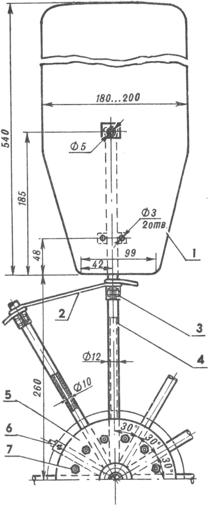
1 — blade, 2 — coupler, 3 — clamp, 4 — supporting spoke, 5 — hub, 6 — thrust spoke, 7 — M8 screw with nut.
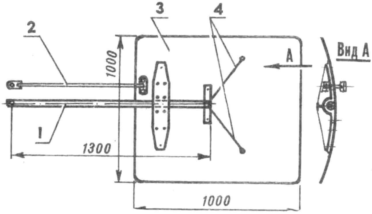
1 – supporting pipe, 2 – rod, 3 – working surface, 4 – guy wires.
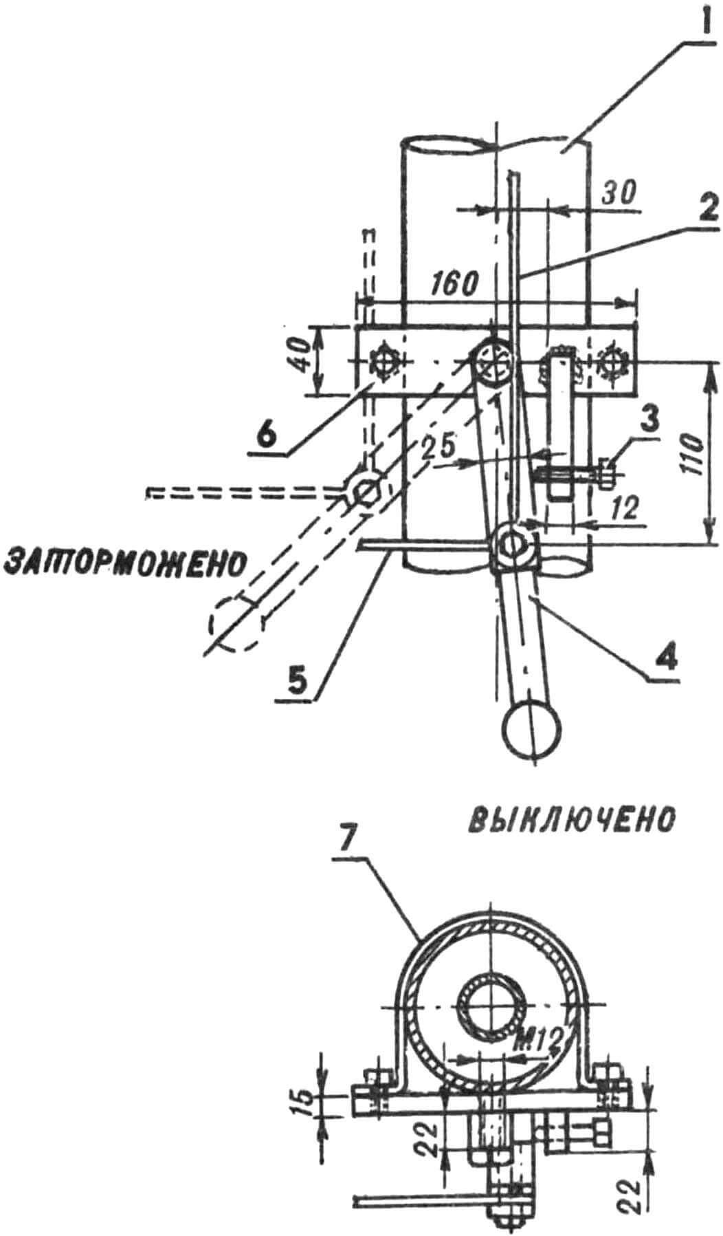
1 — mast, 2 — trigger rod, 3 — M8 adjusting bolt, 4 — trigger lever, 5 — float rod, 6 — flange, 7 — clamp.
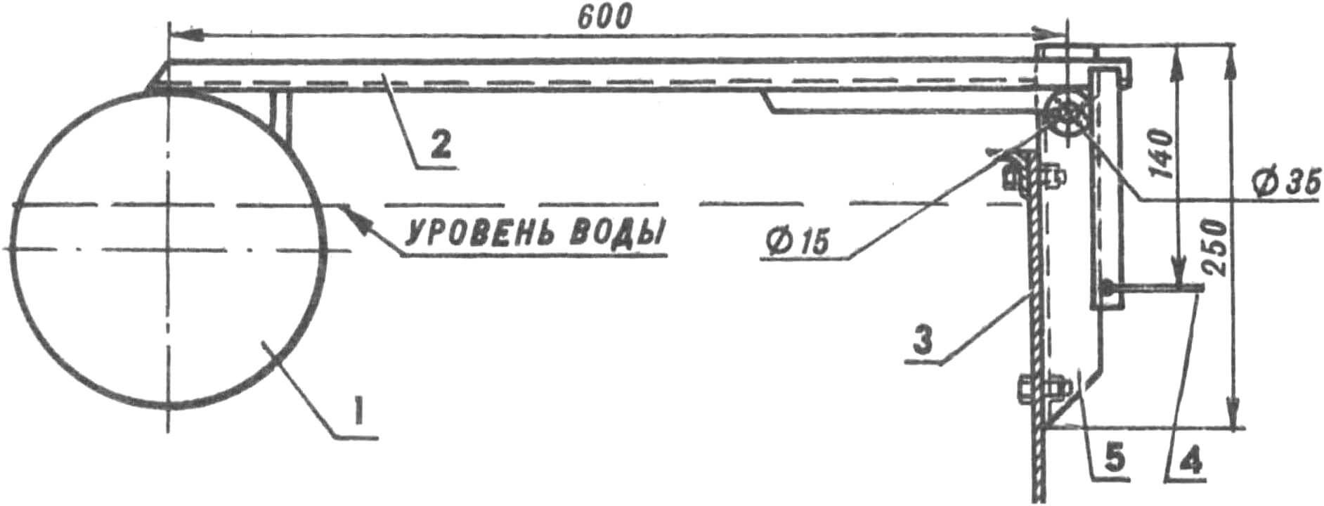
1 – float, 2 – lever, 3 – tank wall, 4 – brake system rod, 5 – mounting bracket.
The pump box is welded from angles and sheet iron 1.5 – 2 mm thick. A household hand pump with a cylinder diameter of 76 mm is fixed inside. So that it could work in a horizontal position, its valves were replaced with rubber spring-loaded ones – as in a general check valve, and the parts of the crank mechanism were replaced with reinforced hardened ones Ø 12 mm, the width of the connecting rod was increased to 10 mm, the stuffing box bushing for the packing was replaced with cast iron – with a double-row rubber seal. With these modifications, the pump worked for four years. Over time, the cast iron piston rings were replaced with polyethylene rings Ø 77 mm. In four years they showed almost no wear, and after replacing the oil seal and pins, they were left in the same set. A hand pump is mounted on the outside of the box. The only changed unit in it is the oil seal; a double-row oil seal was also installed here.
The pump box is mounted on two supports and secured to them with 3-4 bolts.

1 – wind wheel with brake drum, 2 – bevel gear, 3 – shock absorber, 4 – vertical shaft, 5 – brake rod, 6 – brake system release mechanism, 7 – crank mechanism, 8 – pump, 9 – hand pump, 10 – tube well valve, 11 – water tank, 12 – irrigation system pipe.
The principle of operation of the brake system is as follows. When the container is filled with water to the maximum level, the float, through a rod, moves the trigger lever beyond the balance axis, as a result of which the latter ceases to hold the shock absorber spring in a compressed state. The spring will begin to push the pressure ring with the pressure washer upward towards the pusher with the roller. The pressure washer, resting against the pusher roller, turns the lever with the expanding cam, which presses the brake pads against the brake drum. The impeller stops. The pusher roller, rolling along the surface of the pressure washer, holds the impeller in a braked state during any turn when the wind direction changes. The pressure washer is covered on top with a casing that protects the surface of the washer from freezing ice and dirt. The shock absorber was taken from the Voskhod motorcycle and subjected to minor modifications. In order for slow braking to occur, the check valve is caulked and a Ø 1 mm hole is drilled in it (you can directly in the piston) for slow oil flow. The straight valve remains. The threshold of operation of the braking system is adjusted by a screw located on the release device.
Water for irrigation comes from a 12 m deep well. Since the pumps must be constantly filled with water, the well’s check valve is very careful and must hold water throughout the entire irrigation season. In autumn, water is drained from the entire system and the well.
V. SHKURATOV
