Those who keep livestock and poultry in their household cannot do without grain supplies.
Grain can be stored for a long time (I read in one of the magazines that an amphora with wheat was found in some pharaoh’s tomb — the seeds were such that they could be sown). But to use grain as feed for livestock with greater benefit, it must first be ground or at least crushed. However, flour, even coarse, unfortunately, cannot be stored for long under normal conditions: over time it loses quality, becomes rancid, and various bugs and worms appear in it. Therefore, grinding has to be done in small volumes, and quite frequently.
This is where problems arise: industrial mills simply don’t deal with such volumes. Previously, collective farms or farmers helped out, but the former collapsed, and the latter, after struggling, mostly switched to trade.
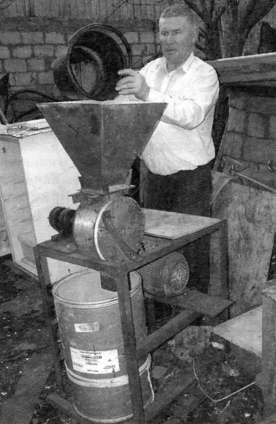
And so owners are forced to acquire some kind of their own mills, grain crushers, or grain grinders — some of industrial manufacture, and some make them themselves. I took the second path.
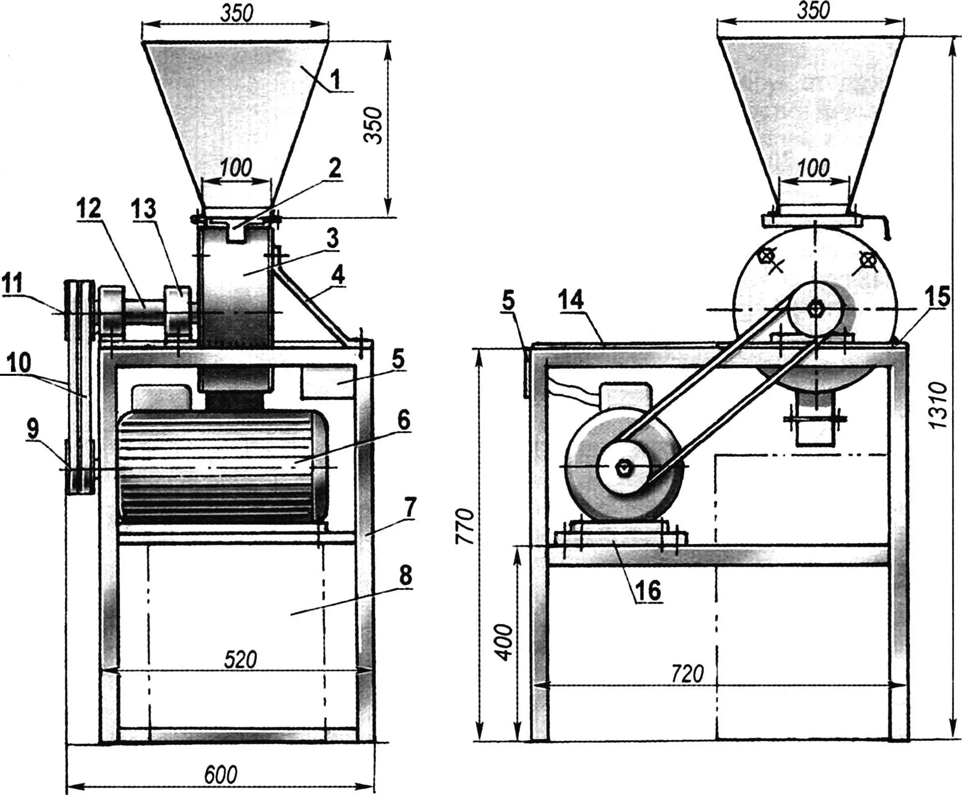
1 — receiving hopper; 2 — sliding gate; 3 — working unit; 4 — brace; 5 — control panel; 6 — electric motor (3-phase, N = 3 kW, n = 3000 rpm); 7 — frame; 8 — container for crushed grain; 9 — drive pulley; 10 — drive V-belts (profile B, 2 pcs.); 11 — driven pulley; 12 — drive shaft; 13 — support bearing 307 in housing (2 pcs.); 14 — cargo platform (asbestos-cement sheet s10); 15 — shaft support platform (steel sheet s6); 16 — electric motor support platform (steel sheet s6)
The grain grinder’s design is, in general, not complicated, one might even say simplified. All units and assemblies are mounted on a simple rectangular frame, the welded frame of which is mostly made of 50×50 mm steel angle. The frame’s support platforms: under the electric motor and bearing housings of the drive shaft are made of 6-mm steel sheet, and the cargo platform-table — from an asbestos-cement sheet 10 mm thick.
The grain grinder’s electric motor with a power of 3 kW and rotation speed of 3000 revolutions per minute operates from a three-phase AC network with a voltage of 380 V.
The transmission of rotational torque from the motor to the drive shaft is carried out by two V-belts of profile B. The pulleys are double-grooved, and the one on the electric motor shaft has a smaller diameter, so the shaft rotation speed is slightly higher than the motor’s — about 3500 revolutions per minute.
Belt tension is produced by moving the electric motor together with the platform on intermediate cross members (stringers) of the frame. The motor on the platform, and the platform on the cross members are secured with four M10 bolts each.
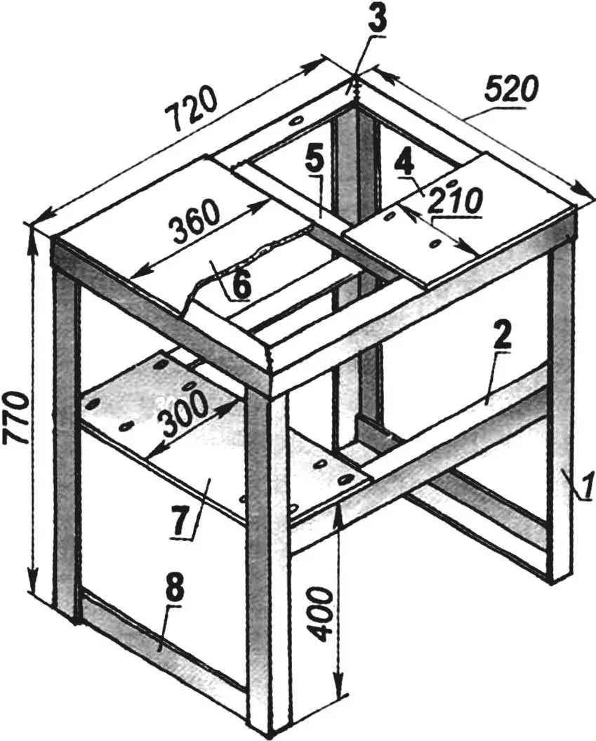
1 — post (angle 50×50, 4 pcs.); 2 — frame stringer (angle 63×63, 2 pcs.); 3 — upper frame binding (angle 50×50); 4 — drive shaft support platform; 5 — upper cross member (angle 50×50); 6 — cargo platform; 7 — electric motor support platform; 8 — lower cross member (angle 50×50, 2 pcs.)
The drive shaft is solid, stepped, I turned it myself from steel 45. On the frame it is mounted on two supports in ball bearings No. 307, each installed in its own housing.
The shaft is cantilevered, that is, the supports are in its middle part. A driven pulley is mounted on one end of the shaft, and a hammer rotor on the other. Both the pulley and rotor are mounted on the shaft with a tight fit with keyed connections.
The loading hopper is made of 1 mm thick steel sheet. It has the shape of an inverted truncated regular pyramid with bases of 350×350 mm and 100×100 mm and a height of 350 mm. Its neck (narrow base) is edged with a welded 25×25 mm steel angle.
The loading (upper) opening of the grain grinder housing has the same edging. During assembly, the edgings are joined through a rubber gasket, and the hopper and housing are pulled together with four M6 bolts through corresponding holes pre-drilled at the corners of the edgings.
The shell — the outer part of the grain grinder housing — is a segment (130 mm) of thick-walled (6 mm) stainless steel pipe with an outer diameter of 270 mm. A stator — a segment of another pipe (of the same length and thickness) — is inserted inside it, the outer diameter of which corresponds to the inner diameter of the first. At the joint of the pipes, four threaded blind holes (sockets) M8 are made on both sides, into which studs are screwed. The side flanges are pulled to the housing by means of studs, and the studs themselves also serve as a kind of keys that prevent the stator pipe from rotating relative to the shell. One flange is blind, and the other — with a hole for the shaft with a seal. The housing flanges are installed on sealant.
Transverse grooves with a cross-section of 4×4 mm are cut on the inner surface of the stator (so that grains are retained in them).
Another rectangular opening (the same as at the top) is made at the bottom of the housing — a discharge opening with a composite outlet pipe — with a short and long one. The joint between the pipes is made the same as in the neck. When unloading crushed grain into a barrel, I remove the lower pipe, and when pouring into a bag — I connect it. The joint also serves as a kind of rib, over which I tie the bag so it doesn’t slip off the pipe.
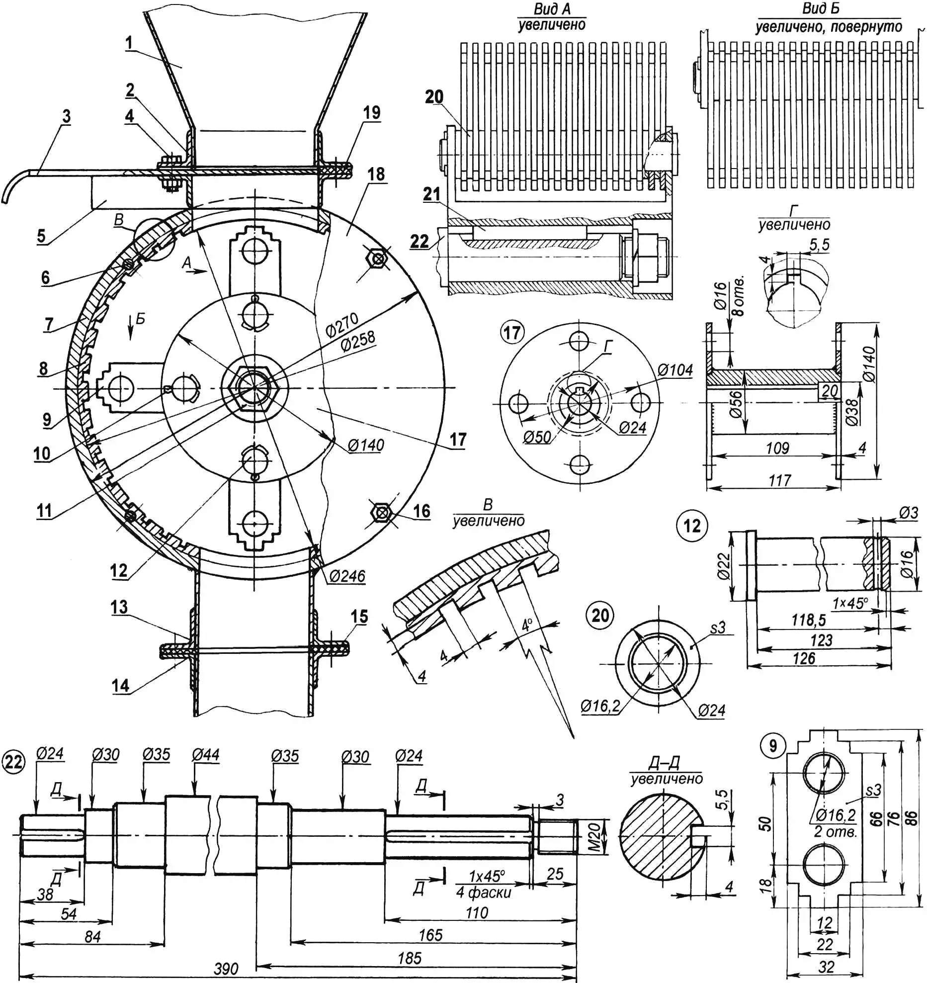
1 — receiving hopper (sheet s1); 2 — receiving hopper neck edging (angle 25×25); 3 — sliding gate (sheet s1); 4 — tie bolt M6 (8 pcs.); 5 — housing loading opening edging (angle 25×25); 6 — stud M8 (8 pcs.); 7 — outer housing shell (pipe Ø270×6); 8 — ribbed stator (pipe Ø258×6); 9 — hammer (sheet s3, hardened to HRC 45-47, 72 pcs.); 10 — cotter pin Ø3 (4 pcs.); 11 — nut M20 with spring washer; 12 — hammer axis (round 22, 4 pcs.); 13 — short pipe edging (angle 25×25); 14 — long pipe edging (angle 25×25); 15 —gasket (rubber, sheet s3); 16 — flange mounting nut M8 (8 pcs.); 17 — hammer rotor; 18 — flange (sheet s5, 2 pcs.); 19 — gasket (rubber, sheet s3); 20 — spacer washer (sheet s3, 72 pcs.); 21 — key; 22 — drive shaft
I welded the housing with tacks to the cross members of the frame.
The most important and complex unit in the grain grinder-crusher is the hammer rotor. I didn’t reinvent it and made it following the pattern and likeness of those that stand in similar, serially produced machines, only reducing the length of the hammers (so they fit in the housing), but increasing their number on the axis.
In addition, I sent the hammers and housing stator for heat treatment, where they were hardened to 45 — 47 HRC units.
When assembling the hammer blocks and spacer washers, I installed them in the rotor so that the gaps between the hammers alternated on adjacent axes.
After mounting the rotor on the shaft, I tightened it further with a nut with a spring washer, and peened the thread at the end in several places with a center punch.
I regulate the grain feed from the hopper to the rotor using a sliding gate installed between the edgings of the hopper neck and the housing loading opening. But very often, having first turned on the grain grinder, I pour grain directly from a bucket or even a bag — the power and revolutions of the rotor are enough to process this mass of grain “on the fly.”
In conclusion, I note that largely thanks to the simplicity of the grain grinder’s design, I use it to grind any dry substances for preparing feed mixtures — from hay to cake.
V. KURAKIN
Recommend to read
 BIKE WIDE PROFILE
In the summer the motorcycle "Minsk" served me faithfully, like the fairytale the little humpbacked horse. In autumn and winter, due to the off-road, it idled, though the need for... ON THE TRACK “MIRAGE”
Usually when we in the club EN-route modeling at the Tushino syt in the beginning of the school year come the newbies, they are already at the first lesson confides that they want to...
