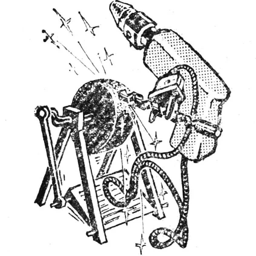
What home craftsman can do without an electric drill? With a set of simple attachments, it can perform a wide variety of material processing operations. But most often, the drill is, of course, used for its intended purpose—drilling holes. How well and quickly you can do this depends on proper tool sharpening. The grinding attachment for sharpening drills that comes with the drill set is not very convenient: holding the drill in the air, it’s quite difficult to correctly sharpen the cutting edges while strictly maintaining their symmetry and the required point angle. But with such an attachment (see fig.), this task is within reach even for a beginner.
The attachment body is a thick-walled steel tube with an outer Ø of 60 mm, length of 125 mm, and wall thickness of 5 mm. The mounting ring, used to install the body on the drill’s mounting neck, has an outer Ø of 50 mm, inner Ø matching the neck diameter, and height of 20 mm. The top cover serves as a jig for the drill being sharpened, which is inserted into the appropriately sized hole. The most complex part to make is the grinding head. A small cylindrical grinding wheel, secured with a nut on a steel mandrel, is clamped in a lathe chuck and its outer face is given a conical shape using a special tool. The point angle will determine the drill sharpening, so it is chosen depending on the material to be processed. For drilling cast iron, the optimal angle is 118°; for viscous low-carbon steels—130°; for aluminum alloys—140°; for plastics and wood—90°. If it’s not possible to make such grinding heads, modify the design: use a cylindrical grinding wheel, and make guide holes in the attachment’s cover-jig at the necessary angle.
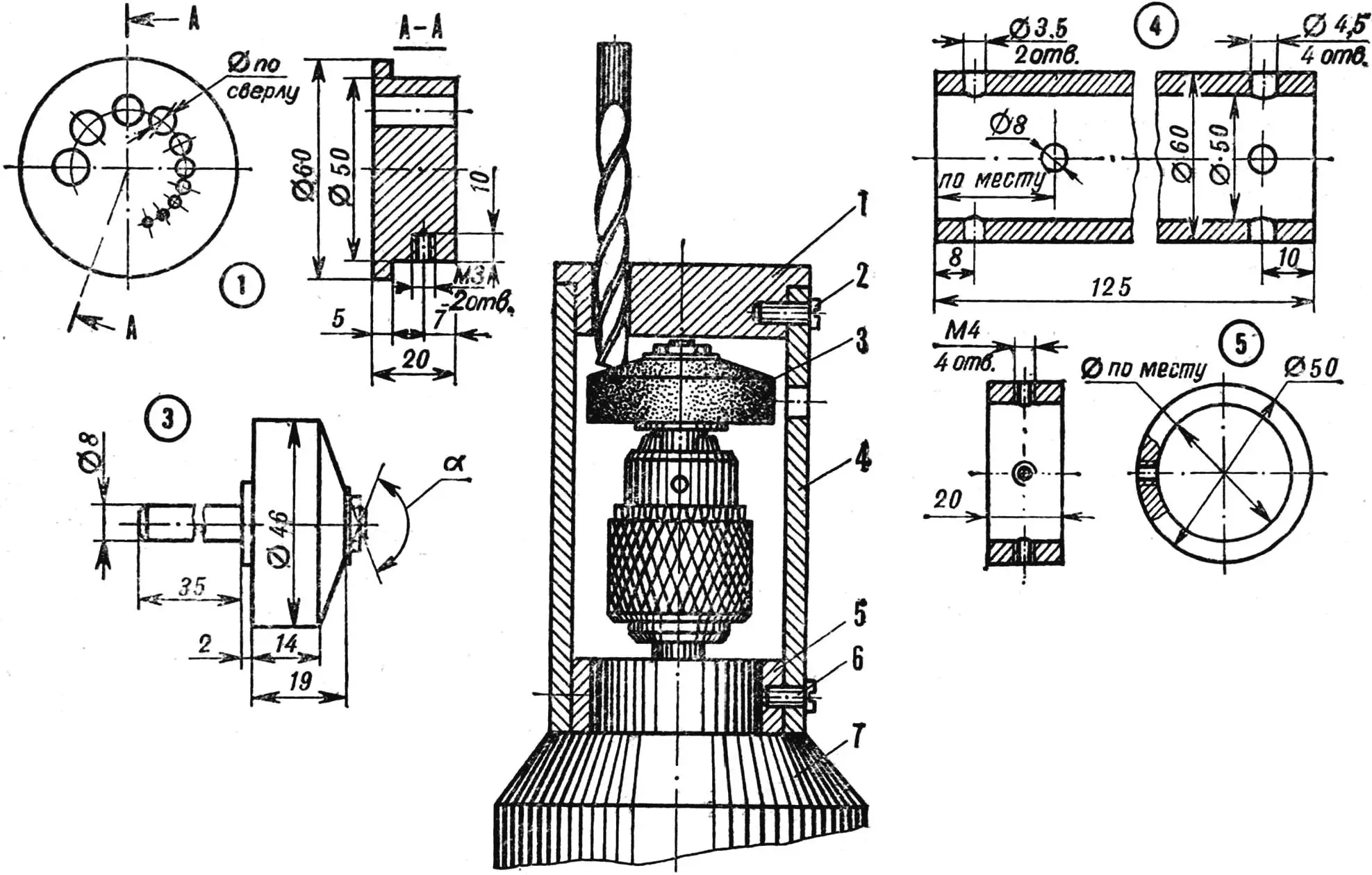
1 — cover-jig, 2 — M3 screw, 3 — grinding head, 4 — attachment body, 5 — mounting ring, 6 — M4 screw, 7 — drill.
The attachment should be assembled in the following order. Insert the cover into the top part of the body and, aligning the radial holes, secure it with two M3 screws. Place the mounting ring on the drill body’s neck, clamp the grinding head in the chuck. Install the attachment body on the drill over the mounting ring and, aligning the radial holes, secure it with four M4 screws.
| GRINDING HEAD POINT ANGLE | |
|---|---|
| Material | α |
| Steel | 130° |
| Cast iron | 118° |
| Aluminum alloys | 140° |
| Wood, plastic | 90° |
Now turn on the drill and, feeding the drill into the appropriately sized hole, begin sharpening its cutting edges. The radial hole in the cylindrical part of the grinding wheel will allow sharpening tools with cutting edges perpendicular to the axis (for example, cylindrical countersinks), as well as facing rods, punches, and drifts.
Based on materials from the magazine “Młody Technik”, Poland
Recommend to read
 HANGING KOLESNICA
Furniture cupboard for shoes, of course, brings a certain order into the hallway. However, if the room is small, then it is in the way. I wouldn't say the original soft "column", which... YOU MECHANIC
SIDE — DUMP TRUCK. To deliver the current grain from working in the field combine to drive if the feed to the farm building materials to the rising walls of the new building is...
