More than once I tried to build a simple, convenient, and compact micro-motorcycle. However, after building and testing several such machines with a D6 engine, shortcomings emerged that were stereotypically repeated in all of them: uncomfortable riding position (especially for tall riders), lack of auxiliary pedal drive, the need to start, as they say, “by pushing,” a small luggage rack… Of course, all this was somehow compensated by the small dimensions and low weight of the machines.
After purchasing a folding bicycle MMVZ “Minsk,” a new idea emerged—to install a D6 engine on it. This promised a number of advantages. First of all, such a bicycle has a fairly comfortable riding position; the ability to adjust the seat and handlebar position within wide limits (both for a child and for an adult). And a normal pedal drive and optimally selected gear ratio from the engine to the drive wheel made it possible to harmoniously combine muscular power and the small power of the D6, achieving good acceleration dynamics and high maximum speed (up to 50 km/h), necessary for riding in traffic. The bicycle also has a decent luggage rack on which various loads can be carried.
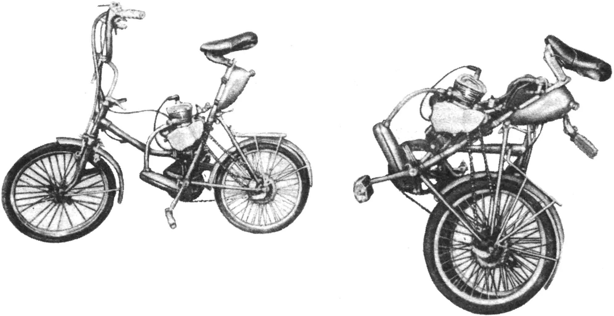
Of course, the main task was such an installation of the engine that would in no way interfere with folding the bicycle. I note that in the folded state, the moped has dimensions that are perhaps even smaller than known micro-motorcycles.
I tried different ways of mounting the engine: on the luggage rack, on the front fork. But in the end, I chose the classic layout: with the engine under the seat. No welding work on the frame was required; I only had to make a few parts, including three simple clamps. I note that the engine can be easily removed at any time.
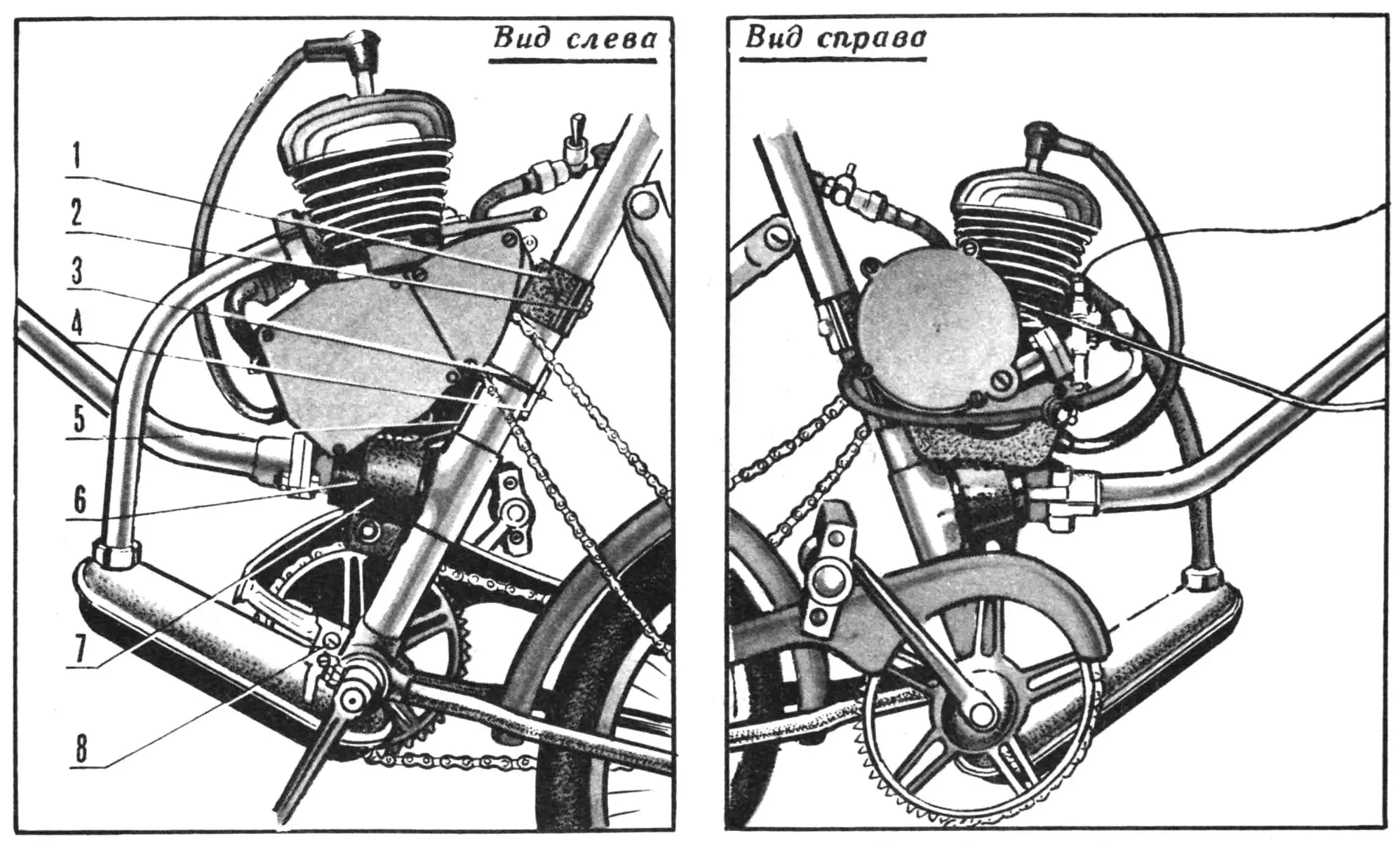
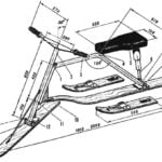
1, 2 — upper mounting unit of the motor installation, 3, 4 — middle mounting unit of the motor installation (extended threaded stud and clamp), 5 — engine base, 6 — gasket (rubber), 7 — lower mounting unit of the motor installation, 8 — adapter plate for muffler mounting.
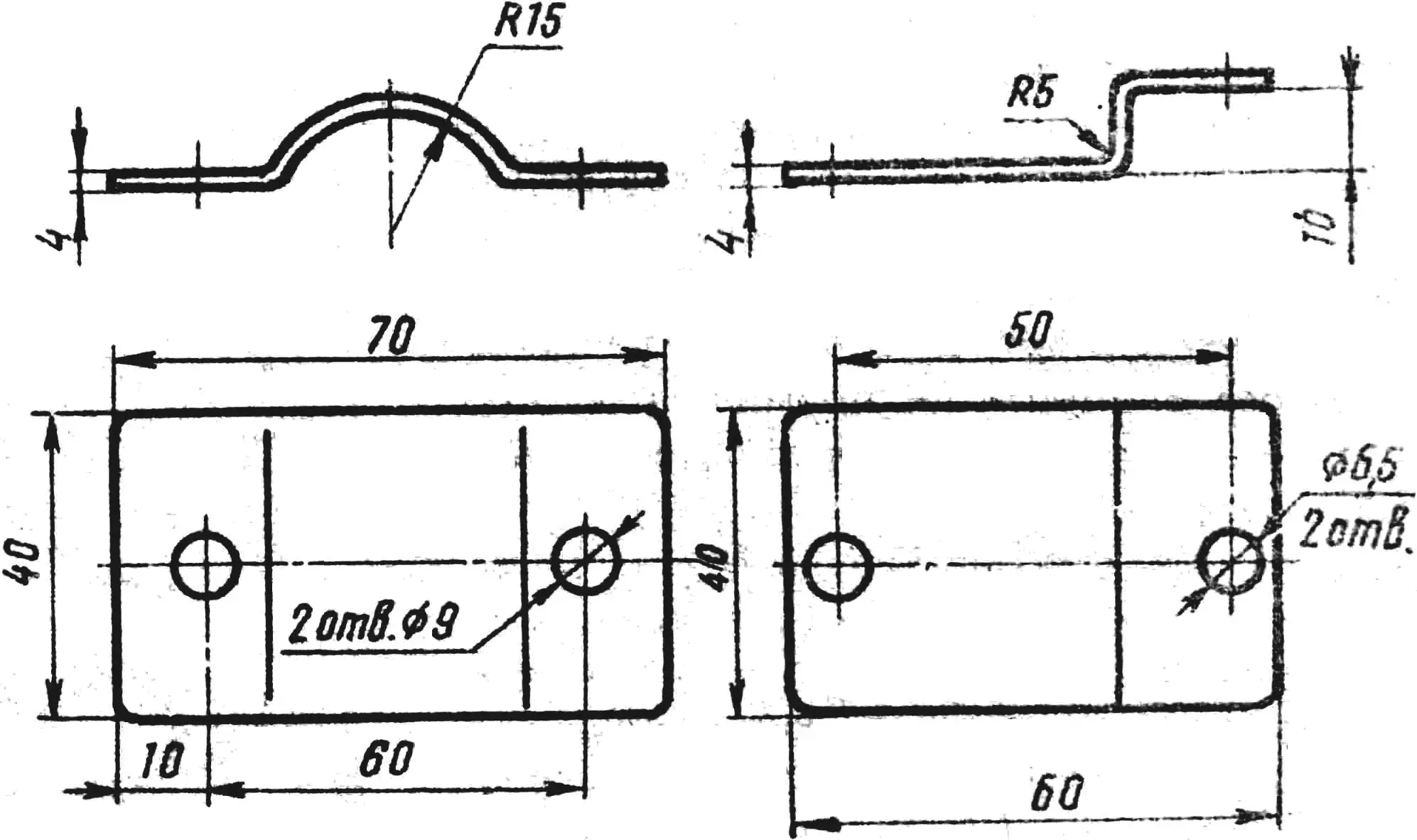
The engine is secured to a base, which in turn is mounted on the frame. The base is welded from sheet steel; it includes a wall and two stiffening ribs that form the basis of the unit, as well as clamps for mounting the base to the frame and a boss-fixer to ensure proper installation of the motor on the base. The boss is a lengthwise-split piece of pipe of suitable diameter. The wall and stiffening ribs are cut from a steel sheet 3.5… 4 mm thick. The wall is first bent along the dotted lines of the development, after which the angles indicated on the drawing are adjusted in place—according to the motor and frame.
A slot is made in the base for passing the left rear mounting stud of the D6, which is replaced with a longer one—50 mm (due to the large diameter of the bicycle’s seat tube).
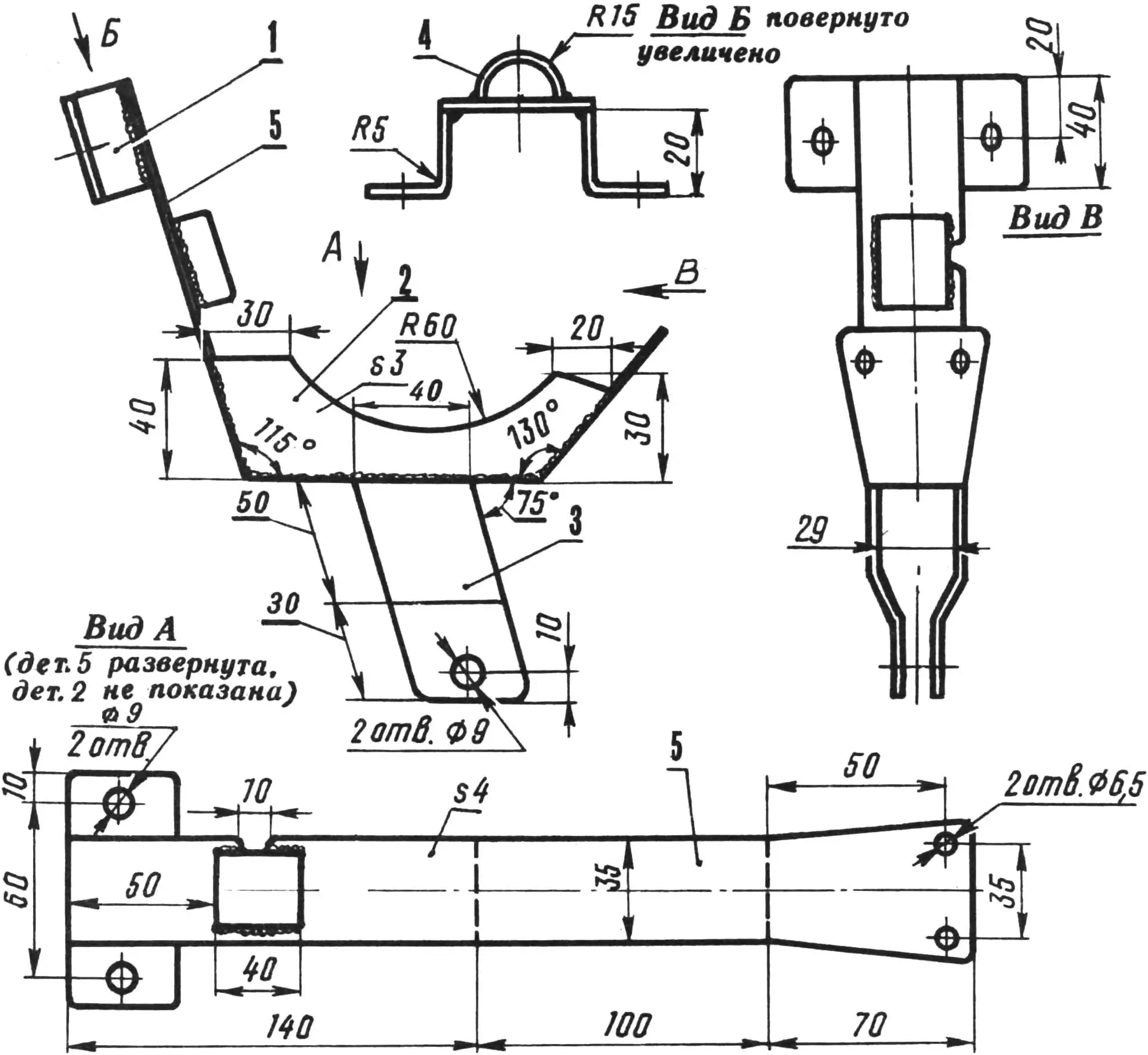
1 — lugs of the upper mounting unit of the motor installation, 2 — stiffening ribs, 3 — clamp of the lower mounting unit of the motor installation, 4 — boss-fixer, 5 — wall.
For the same reason, the standard rear right engine mounting stud is moved 15 mm to the right (for which a hole is drilled in the crankcase and M6 thread is cut). The adapter is attached to the frame with a clamp with a rubber gasket (a strip of rubber from an auto inner tube), which is tightened with an M8 bolt. The top of the base is also secured with a clamp and two M8 bolts. And a clamp is put on the engine studs, fixed with M6 nuts.
The muffler is standard. It is only necessary to slightly straighten the exhaust pipe (by heating it in the flame of a blowtorch) with fitting in place. The lower end of the muffler is attached to the chain guard lug (on the bottom bracket) through a small plate, the dimensions of which are selected in place.
The driven sprocket (Z=22) is from a “Sputnik” sports bicycle. With such a sprocket, the bicycle moves steadily at speeds from 15 to 50 km/h, however, when starting from a standstill and accelerating, the rider needs to work with the pedals as well.
The sprocket mounting is conventional: with half-rings to the rear wheel hub of the bicycle. To protect the spokes and prevent the chain from coming off, a disc made of two-millimeter steel sheet is inserted between the sprocket and the spokes. Its outer diameter is 140 mm, inner—according to the hub diameter.
When installing the chain drive, it may be necessary to slightly bend the inclined tube of the rear fork. For this, the wheel is removed, the bicycle is placed on stands (wooden blocks), and with two or three blows through a wooden spacer, a slight bend of the tube is achieved, thanks to which the chain does not catch on it.
The controls are standard, without modifications, located on the handlebar. The fuel tank is of the “droplet” type; however, another suitable container can be used. The tank is suspended on the seat tube.
To increase riding safety, the bicycle is equipped with a duplicated hand brake acting on the front wheel. An additional one is added to the standard brake, attached to the reverse side of the front fork with an extended stud. Both brakes are controlled by a lever located on the handlebar on the right.
The bicycle’s running gear was not modified, no reinforcements to its structure were made. Over 8 years of operation, the total mileage amounted to more than 10 thousand km on asphalt and dirt roads, with the total “load” reaching 140 km. No destruction of frame elements or welds was observed.
Changes affected only the tires. A “mesh bag” cut from an old tire was put over the standard tire: thus, a tread with a deep pattern appeared on the rear wheel, which is useful when riding on dirt. When tire wear became significant, two tires were put on both the front and rear wheels: an old one on the bottom, a new one on top. This improved shock absorption on uneven surfaces.
In conclusion, it remains to add that the bicycle was used both for long trips between cities and for everyday riding. The design turned out to be very “durable” and reliable.
This is the folding moped I offer to the readers’ attention. I am sure it will be useful to many, especially beginners, primarily due to its simplicity and reliability. (By the way, my machine is simpler than Pankov’s, who described it in “M-K” No. 3 for 1985.)
V. KOROBOVSKY, engineer
Recommend to read
 SCOOTER IN THE SNOW
Snow scooter we recommend that you do, will give the opportunity not only to descend from the snowy mountains, but to engage in the slalom. To build it is not too difficult. Well, of... FUNNY CALL
Unenviable situation: come visit, but to notify owners about it difficult due to bad changes in our life, when the apartment began to remind of a fortress or prison with armored...
