For soil cultivation, many mechanical devices have been created to greatly facilitate this process. There are motor-ploughs, micro-tractors, and mechanized hoes… Of course, each such unit is designed for processing certain areas: a motor-tractor, for example, is convenient for fairly long runs, a motor-plough is more suitable for smaller plots, but it’s best not to plow small beds, but… mill. The purpose of our publication today is precisely to introduce you to the design of a simple rotary cutter. Any engine from the Sh series (Sh-52—Sh-58) with a cylinder displacement of 50 cm3 can be used as a power unit for it.
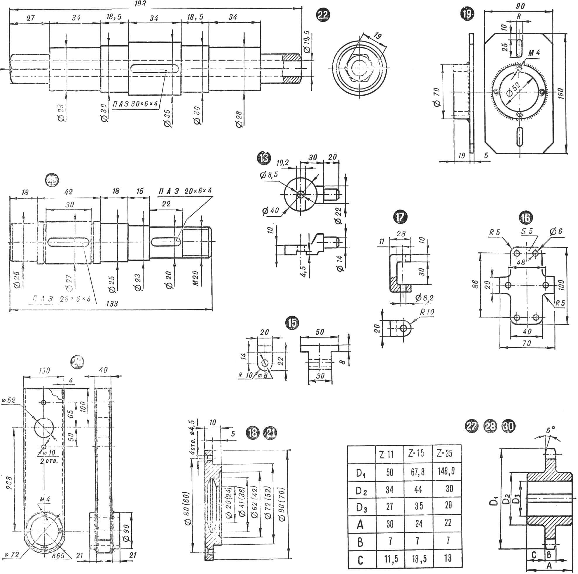
The cutting tool (mill) of the unit is assembled from steel strips with a section of 5X40 mm. Each of the cutters will require eight of them. The strips are bent in the shape of the letter L and connected to each other with M6 bolts, forming four crosses. The latter are welded in pairs to two bushings having internal holes in the form of hexagons.
The basis of the rotary cutter frame is a steel box in which one of the deceleration stages of the chain gearbox is located. The box is welded from 4 mm thick plates and two bearing housings located in its lower part. In the upper part of the box, two holes are cut through which the intermediate shaft passes. The latter rotates in two bearings (205), located in two housings, each of which is welded from a steel plate 5 mm thick and a steel ring. The housings can move around the box due to the oval holes on the plate – this makes it possible to tension the chain connecting the sprockets of the working and intermediate shafts. To fix the selected position, there are two threaded rods welded to the plastic bases, a plate with slotted holes and two nuts with washers.
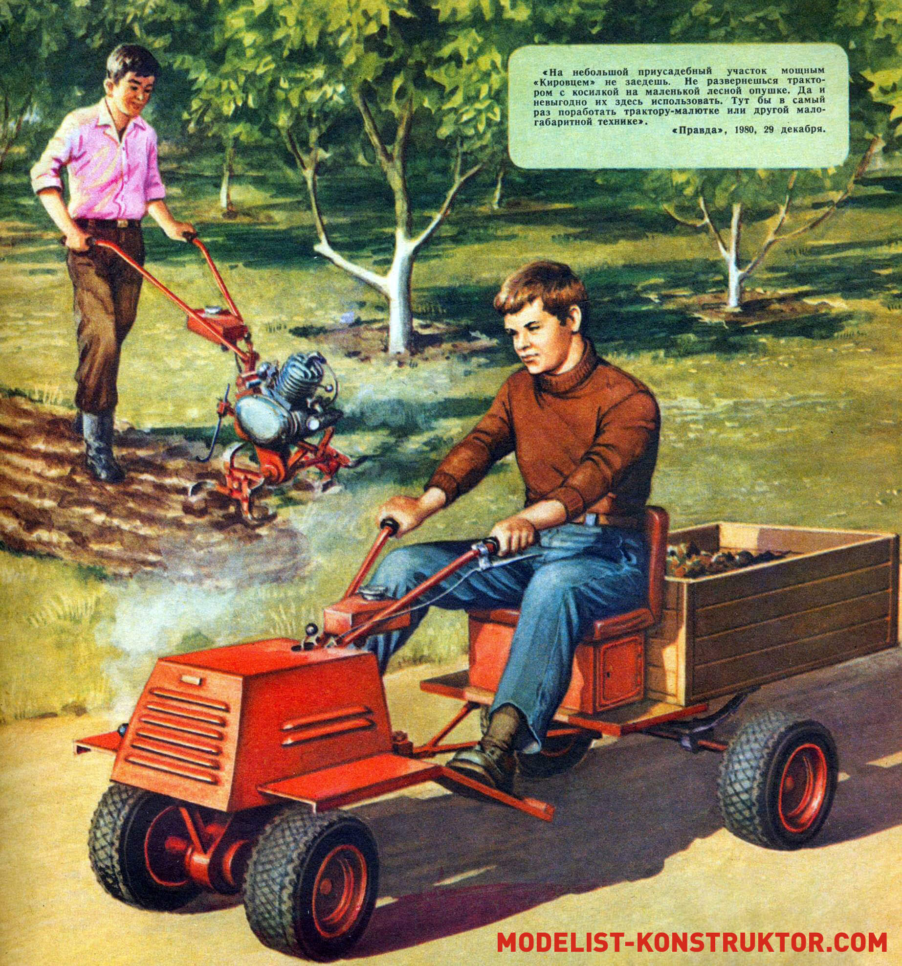
This is exactly the kind of station wagon you need for your backyard “field”! Loosening the soil with a milling cutter allows you to literally perform jewelry processing of tree trunk circles, small ridges, and, if necessary, sufficiently deep plowing of plots. Half an hour of work – and the milling cutter turns into a motorized towing vehicle, capable of transporting about a hundred kilograms of any cargo.
The engine is mounted on a bracket welded to the front of the box. The horizontal and vertical parts of the bracket are sections of a steel “T” profile, the strut is a steel strip with a section of 5X40 mm. On the vertical part of the bracket there are two brackets made of a 5 mm thick strip – the engine is attached to them with two bolts with M8 threads.
The handles of the rotary cutter are curved from two steel pipes with an outer diameter of 22 mm. Between the handles there is a fuel tank with a capacity of about 2 liters, soldered from galvanized roofing iron.
The handles are attached to the frame through an adapter – a roller with two flanges and a split pipe-clamp with a clamping handle. The pipe clamp is fixed to a stand welded to the frame box of the milling cutter.
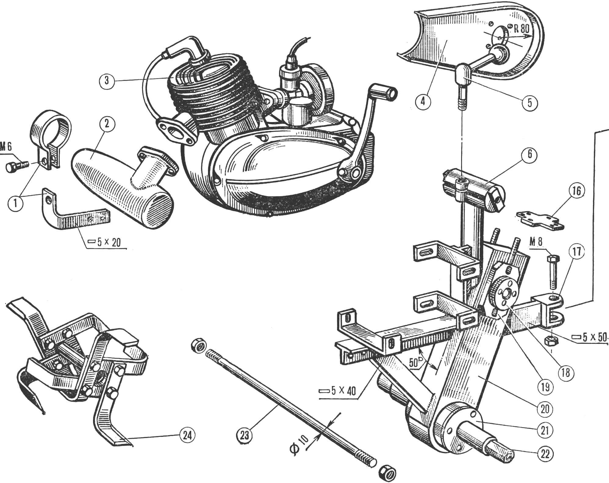
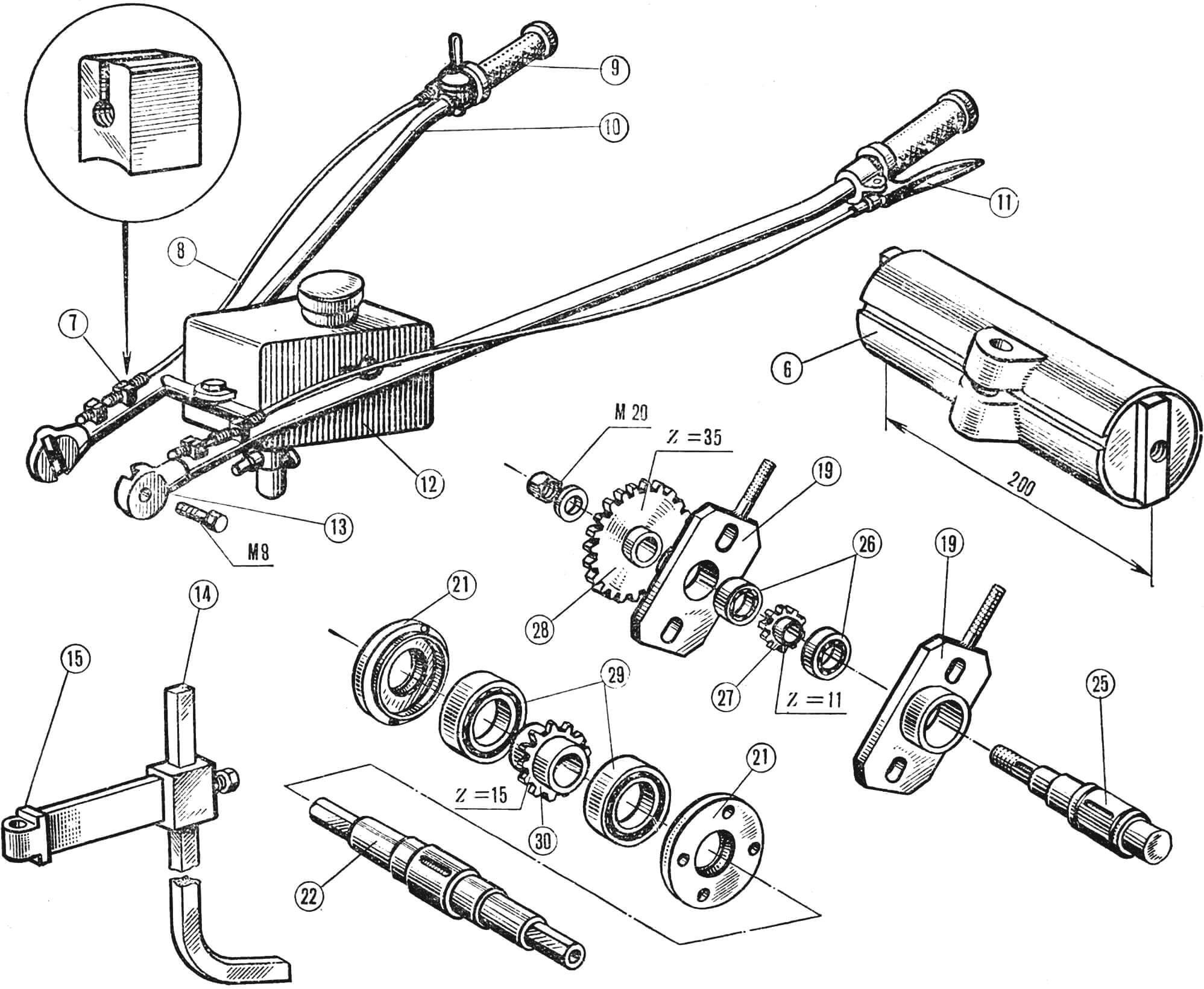
1 — muffler mounting bracket, 2 — muffler, 3 — engine, 4 — chain protective cover, 5 — locking handle, 6 — rotation mechanism for the engine handles, 7 — engine control cable tension regulator, 8 — control cable, 9 — throttle handle “, 10 — handle of the motor unit, 11 — clutch release handle, 12 — fuel tank, 13 — adapter, 14 — “crutch”, 15 — bracket, 16 — thrust plate of the chain tension mechanism, 17 — coupling fork, 18, 21 — covers, 19 — intermediate shaft bearing housing, 20 — frame box, 22 — working shaft, 23 — coupler, 24 — cutter, 25 — intermediate shaft, 26 — bearings 205, 27, 28 — intermediate sprockets, 29 — bearings 306, 30 — working shaft sprocket.
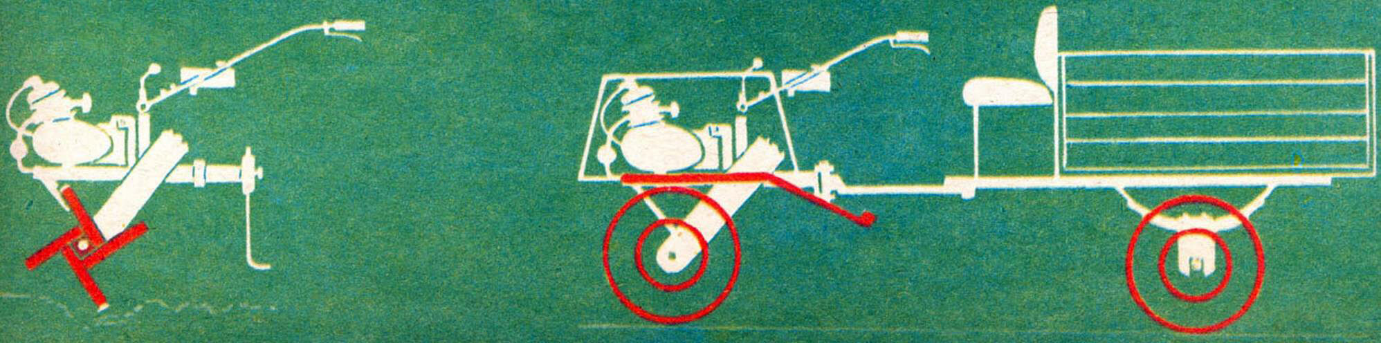
At the rear of the frame there is a coupling device – a steel strip with a U-shaped bracket welded to it. When using a rotary cutter in the basic version, a brake spike is hinged in the coupling device, with the help of which the speed of movement through the arable land and the degree of tillage are regulated. When using the unit in the version of a motor tractor (together with a transport trolley), instead of a crutch, the eye of the trolley carrier is fixed. Naturally, in this case, instead of cutters, wheels are installed on the working shaft.
The milling cutter will require three sprockets – two of them (Z-35 and Z-11) are located on the intermediate shaft and one (Z-15) on the working one. All sprockets are machined from steel, but a welded design is possible: the hub is a section of a suitable pipe and the disk is a steel plate 7 mm thick.
When assembling the unit, special attention should be paid to the installation of the engine: the axis of its sprocket must coincide with the axis of the sprocket on the intermediate shaft. For convenience, make the engine mounting brackets wider than the lugs on its crankcase and use spacers during assembly – this will help to more accurately align the planes of the sprockets.
If after starting the engine you find that it is overheating, you will have to construct a simple fan. For engines of the Sh series, this is quite simple – a hole is cut in the crankcase cover, coaxial with the magneto flywheel, and the centrifugal fan impeller is fixed to the latter. The volute and air duct can be knocked out from an aluminum sheet.
It is best to hood the engine – for this you will need a sheet of roofing iron or duralumin, bent in the shape of the letter P. Cover the cutters (wheels) with mud shields.
The engine controls are no different from the stock ones. On the handles of the milling cutter there are mounted handles for the gas, clutch, and speed switch. The engine is started manually using a kickstarter.
The transport trolley is assembled on a tubular frame. A body assembled from ten-millimeter plywood with the help of duralumin or steel corners is attached to it. The driver’s seat is installed directly in front of the body – for this purpose it is best to use the frame of an old metal chair. The wheels of the transport trolley must be equipped with drum brakes; the handle of their drive is fixed on the trolley itself.
“You can’t drive a powerful Kirovets into a small plot of land. You can’t turn around with a tractor and mower on a small forest edge. And it is not profitable to use them here. This would be the perfect place for a small tractor or other small-sized equipment to work.”
“Pravda”, 1980, December 29.
(Based on materials from the Hungarian magazine “Ezermeshter”)
Recommend to read
 A QUICK SAUNA
Building this sauna is not too difficult. It retains heat perfectly, is bright and spacious inside, and steaming here is much more enjoyable than in the well-known tourist steam room made... THE DRILL TEAM
Having a pretty powerful compact drive, the electric long gone among the leaders of household tools. And with the attachments, all kinds of fixtures are not averse and in agricultural...
