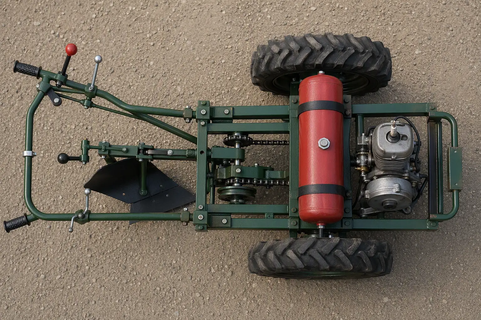
Isn’t it a striking contrast: while the fields of collective and state farms are cultivated today by powerful “Kirovets” tractors, the household plots of rural workers are still plowed the old way — in the best case with a horse-drawn plow, and in the worst simply dug up with a shovel. This work is unproductive, takes a great deal of time, and also requires considerable physical effort. That is why many DIY builders, without waiting for industry to master the production of small agricultural machinery, design and make motor plows and microtractors, motor cultivators and mechanized hoes. In today’s publication you can get acquainted with the drawings and description of a homemade motor plow designed by pump-plant worker V. I. Petrunya from the settlement of Svessa in the Yampol district of Sumy region. The design, although it does not meet all the requirements of modern styling, is quite reliable and fully lives up to the name of a motor plowman.
Almost all parts of the motor plow are homemade, but they are not too complex, and anyone with metalworking skills can make them.
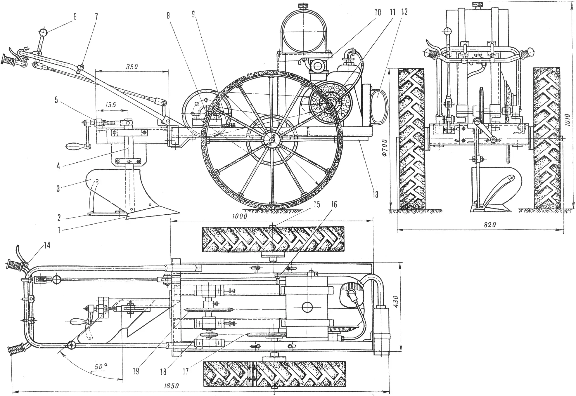
1 — share, 2 — runner, 3 — moldboard, 4 — bracket, 5 — screw, 6 — gearshift lever, 7 — engine stop button, 8 — intermediate shaft, 9 — chain tensioner, 10 — engine air filter, 11 — engine magneto, 12 — muffler, 13 — counterweight, 14 — handlebars, 15 — motor plow wheel axle, 16 — engine starting handle, 17 — sprocket (Z = 45, t = 19.05 mm), 18 — sprocket (Z = 15, t = 19.05 mm), 19 — sprocket (Z = 62, t =12.7 mm).
The basis of the motor plow is a frame welded from steel angle bar 50X50X5 mm. The engine, drive axle, plow and controls are mounted on it.
The wheels are homemade. Each consists of a central hub, twelve spokes made of Ø 14 mm steel rod, a rim (a steel strip 6 mm thick and 120 mm wide) and a rubber-cord tire tread with a coarse pattern cut from an old automobile tire.
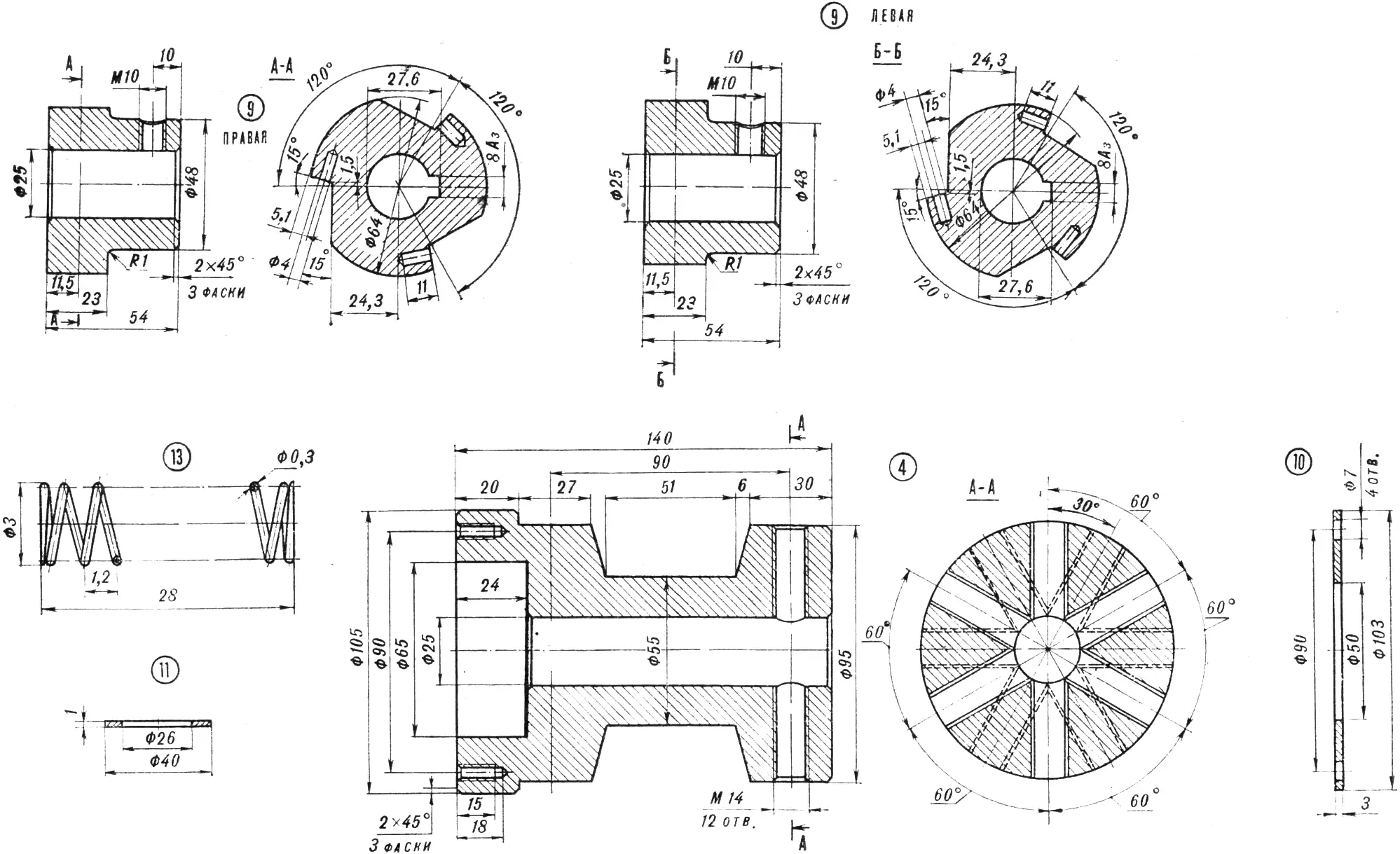
The central hubs of the wheel are fitted with freewheel clutches — this is much simpler than a differential and more reliable than a single drive wheel. The wheel is assembled as follows. The spokes are screwed into the hubs, and a nut is threaded onto each one. Then the spokes are passed in sequence through the holes in the steel rim strip and each is fixed from the outside with a second nut. After balancing and centering, the rim is welded or fastened from the inside with a splice plate and screws. To secure the tire, two angle pieces are fitted to it; each has two holes through which M10 clamping bolts are passed.
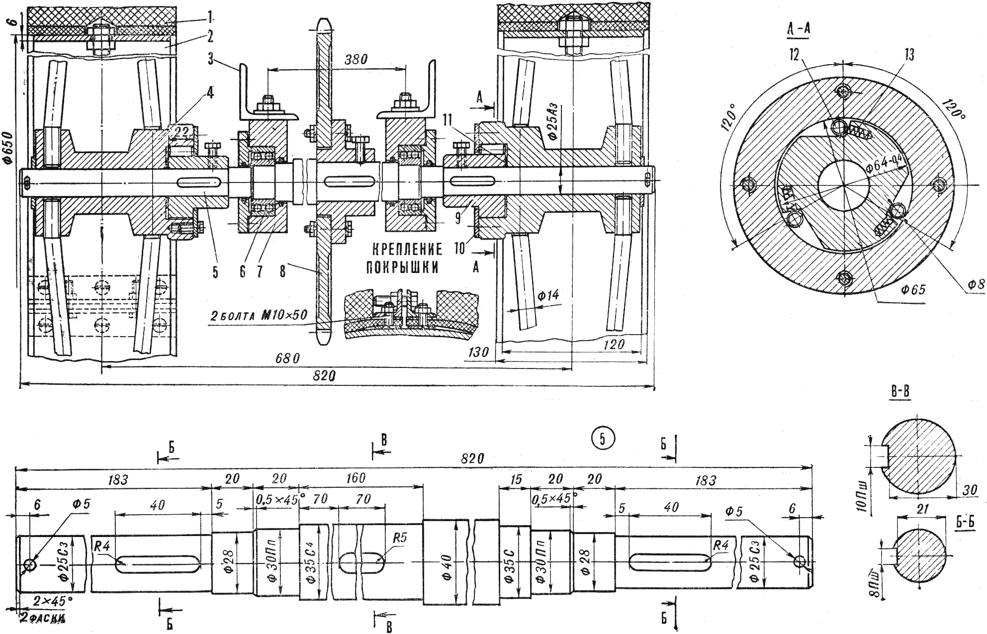
1 — treaded wheel tire, 2 — wheel, 3 — frame, 4 — freewheel clutch, 5 — axle, 6 — bearing No. 1506, 7 — bearing housing, 8 — sprocket (Z = 45), 9 — half-coupling, 10 — cover, 11 — washer, 12 — roller, 13 — spring.
The drive axle is turned from Ø 40 mm bar stock (Steel 40). It is best done between centers, paying attention to the seating surfaces — their finish should be no lower than class 7, and the accuracy class no less than 2. The same applies to the intermediate shaft as well.
The motor plow uses a two-stage chain reduction gear. The gear ratio of the first reduction stage is 3.65, of the second — 3. These figures must be strictly observed: at this gear ratio the motor plow’s speed is about 4 km/h.
All sprockets of the chain reduction gear are homemade. They are connected both to the intermediate and to the drive shaft with keys.
Special attention in making the motor plowman should be given to the plow itself. Inaccuracy in its “geometry” can undo all the work done, because such a plow will not till. The main thing is to set the moldboard correctly — that is, the part that turns the soil over. The optimum angle is 50°: at a smaller angle soil resistance rises sharply, which will cause slipping and vibration of the whole unit.
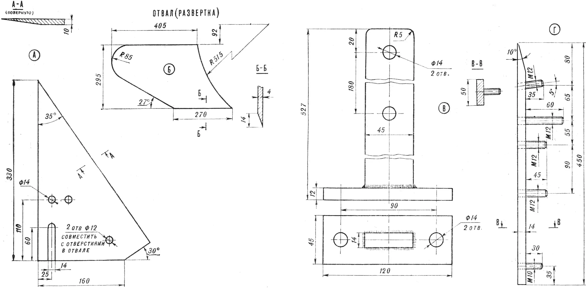
A — share, B — moldboard (development), C — lever, D — runner.
The plow is mounted on the frame so that the tillage depth and the setting angle can be changed. This is done with a handle; when it is turned, the plow pivots on the lever, raising or lowering the point. Its position can also be adjusted on the move.
The plow is attached to channel No. 10 at the rear of the frame. The working width can be changed; for this the channel has slots through which the working tool is fastened with M12 bolts.
The motor plow’s engine is from a T-200 scooter. Its layout poses no special difficulties. Controls are brought out to the handles.
Besides its main purpose, the motor plow can also be used with a single-axle trailer for hauling various loads.
“M-K” 10’79, V. PETRUNYA
Recommend to read
 HOOD-INVISIBLE
For many years I am a subscriber of the journal "modelist-Konstruktor". Many find useful for themselves. Some of the ideas I use is from the column "the Club house masters", and today he... TO NOT UNSCREW THE SCREW
To nut the connections didn't loosen during operation of the device, usually put the second (jam nut) or enclose the washer Grover. If such is not at hand or you need to fix the little...
