This very “flyable” radio-controlled powered hang-glider model was designed specifically for beginners: it is not difficult to build, and it is practically impossible to wreck on landing.
A wide variety of materials can be used to make the model — from balsa to basswood (linden). For the formers, even ordinary packaging foam will do, for example, faced on both sides with 1 mm plywood or pressboard (electrical cardboard). Fragments of previously wrecked models, which usually accumulate in considerable numbers among modelers, especially in clubs, can also be put to use.
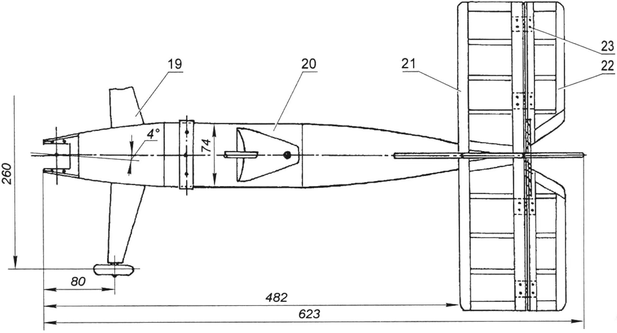
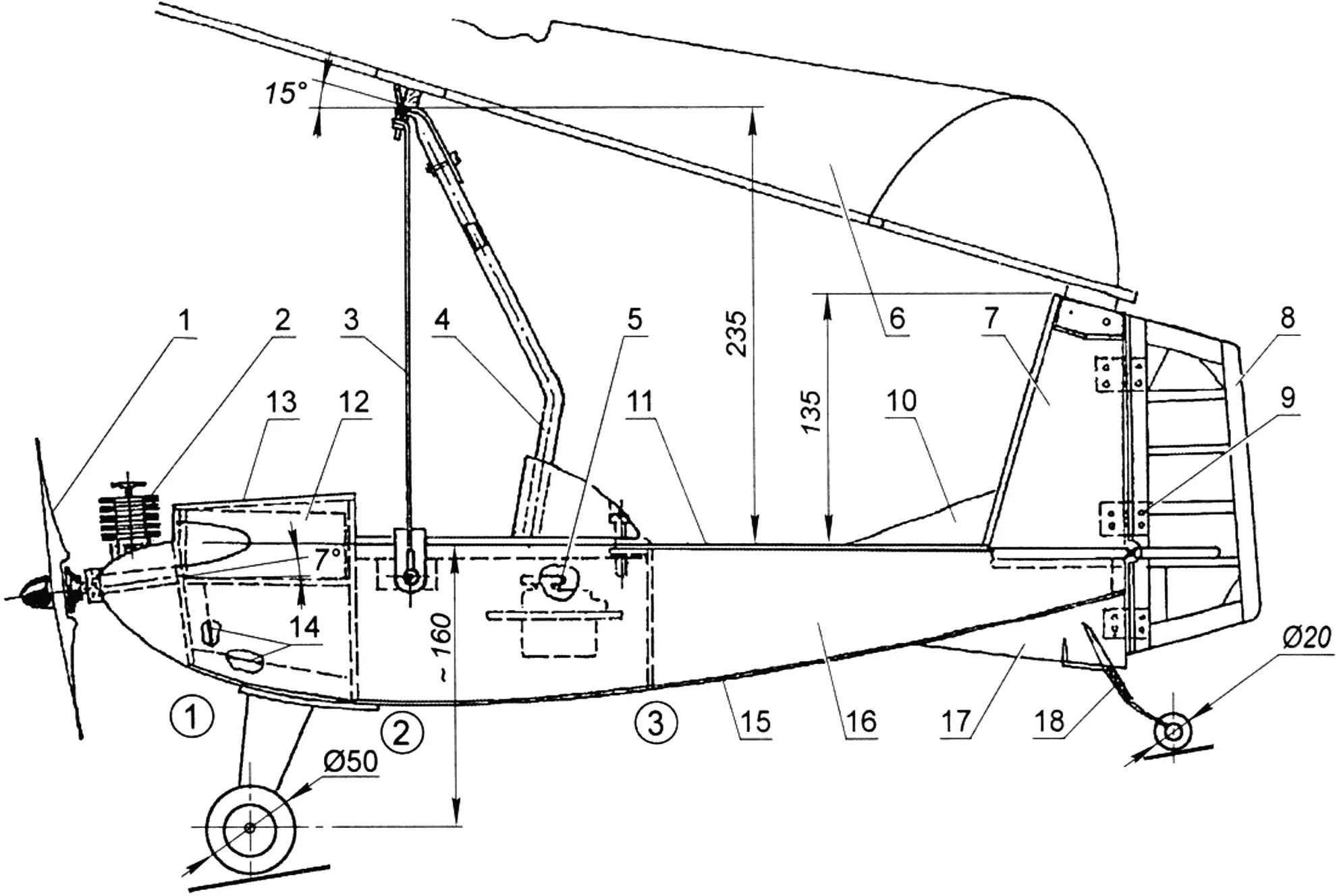
1 — propeller; 2 — engine 1.5–2.5 cc; 3 — brace wire (Ø0.3 mm); 4 — pylon (tube Ø8×1 mm); 5 — servo block; 6 — wing; 7 — fin; 8 — rudder; 9 — rudder hinge; 10 — ventral fin; 11 — upper fuselage panel; 12 — fuel tank; 13 — fairing; 14 — forward fuselage frame; 15 — lower fuselage panel; 16 — side fuselage panel; 17 — bracket; 18 — rear landing-gear strut; 19 — nose landing-gear strut; 20 — central fuselage unit; 21 — horizontal tail; 22 — elevator; 23 — elevator hinge
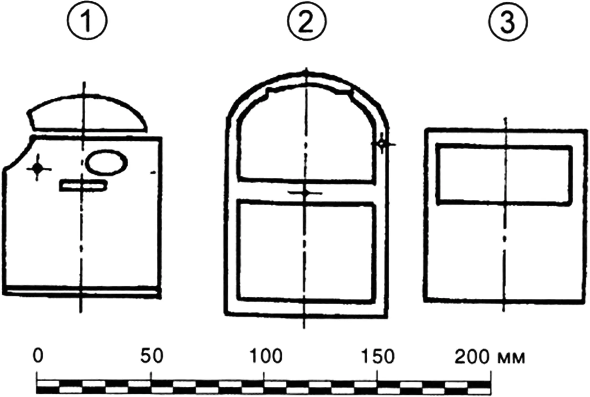
First, draw a full-size fuselage drawing on a sheet of graph paper — it will be needed when laying out the model (it will serve as a building board/pattern) and later during assembly.
Following the pattern, cut three formers from balsa (s4–5 mm), basswood (s3 mm), or foam blanks (s6–8 mm). Next, prepare the fuselage side panels from basswood or balsa veneer, 1 mm plywood, or pressboard. Fit the parts to one another and glue them with epoxy resin. Pins, clothespins, and rubber bands are used for temporary fixing. Glue the upper and lower panels to the frame — the fuselage base is ready.
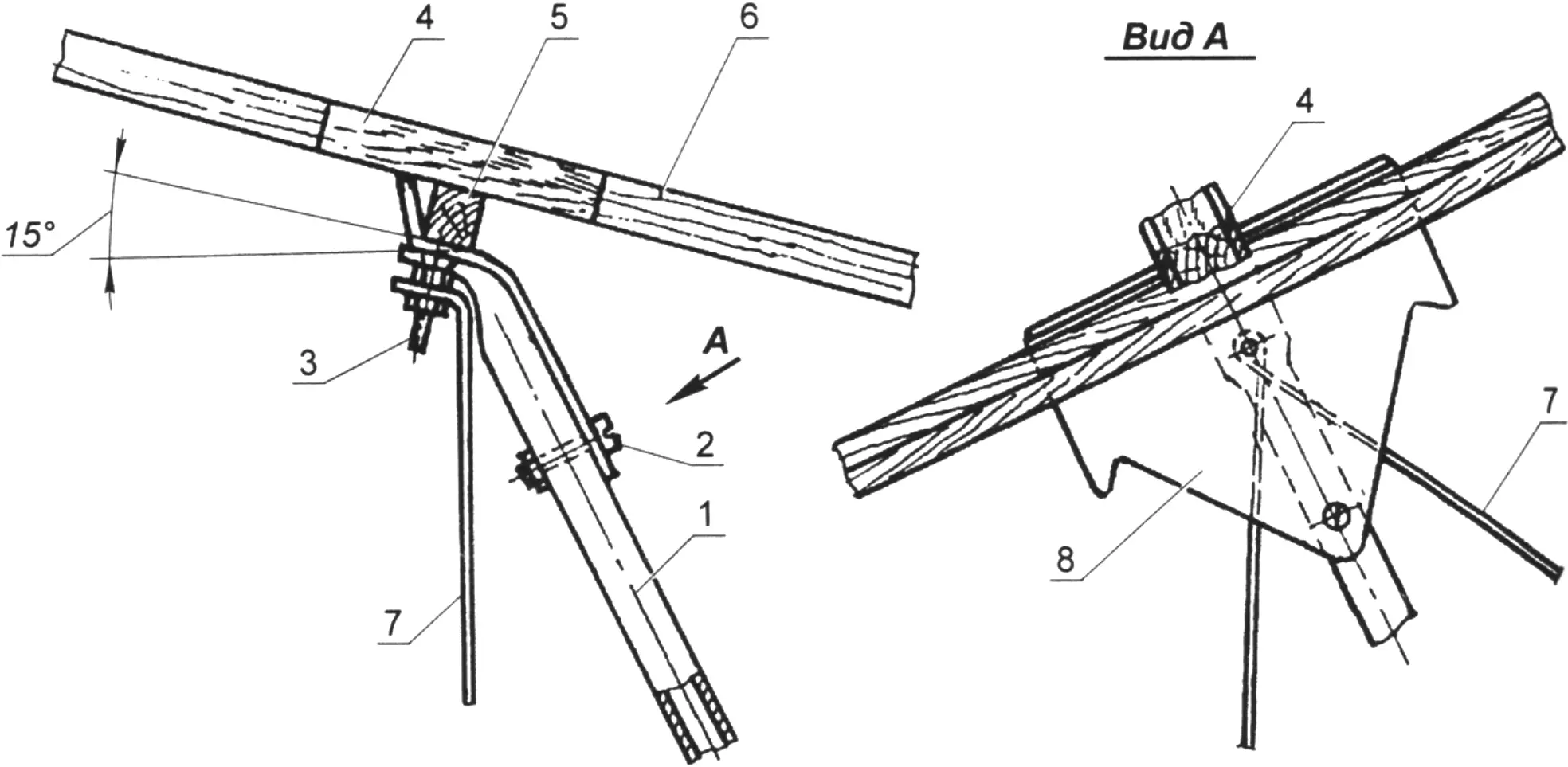
1 — clamp (duralumin s2 mm); 2 — M2 bolt; 3 — sleeve (duralumin tube Ø10×1 mm); 4 — block (basswood); 5 — plate (plywood s3 mm)
The fin and horizontal tail are assembled from balsa or basswood strips of 12×6 mm and 6×6 mm cross-section. The rudder and elevators are attached to the fin and horizontal tail, respectively, with nylon hinges. The fin and horizontal tail are covered with Mylar film using the standard technique with BF-2 adhesive and an electric iron.
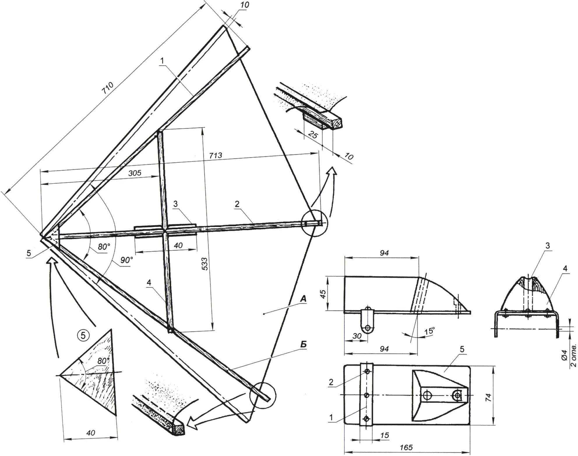
1 — side spar (spruce, strip 7×7 mm); 2 — center spar (spruce, strip 7×7 mm); 3 — doubler (plywood s2 mm); 4 — cross spar (spruce, strip 7×7 mm); 5 — gusset (plywood s1 mm)
The delta-wing frame is assembled from good-quality spruce strips of 7×7 mm cross-section. At the front it is reinforced with two plywood (s1 mm) gussets. Two plywood doublers also reinforce the center spar where it is crossed by the cross-member. The wing is covered with Mylar film, bonded to the side and center spars with BF-2 adhesive. It is preferable to use tinted film for the delta — orange, black, or multicolored: the model will be visible from a distance, which will make it easier to control.
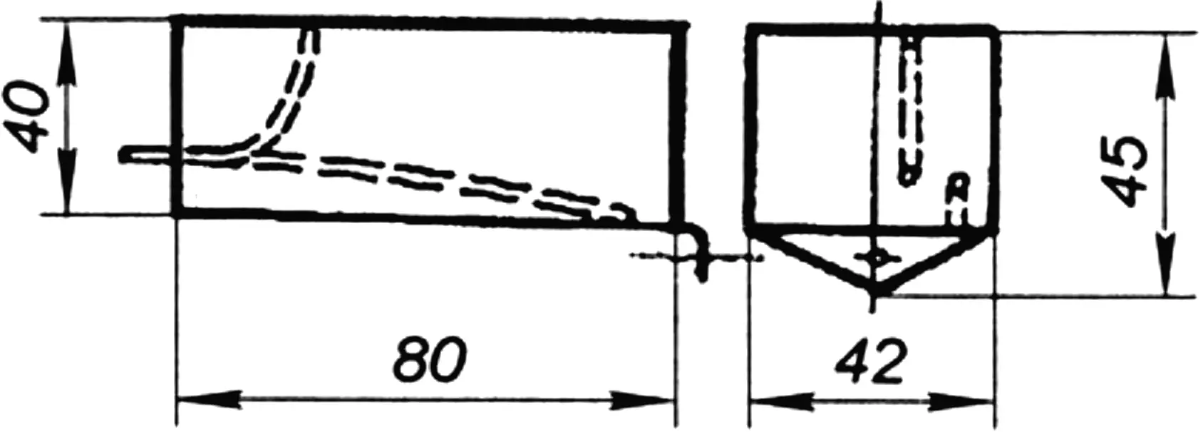
The wing is attached at two points: on the pylon and on the fin. The pylon is a bent duralumin tube Ø8×1 mm, fixed in a block on the fuselage and secured with two brace wires of Ø0.3 mm. The cross spar is fixed on a cradle made of 1 mm sheet duralumin.
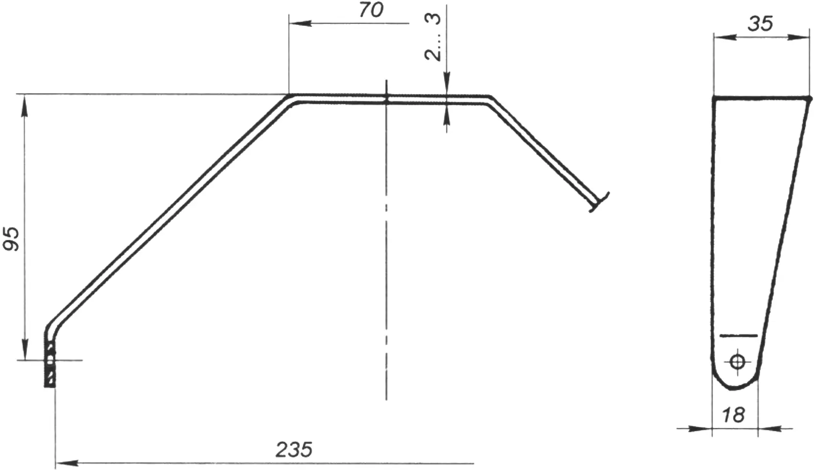
The nose landing-gear strut of the model is bent from a duralumin strip 2–3 mm thick. Plastic wheels Ø50 mm can be taken from a children’s toy; the tail wheel is Ø20 mm.
The model is designed for a glow or diesel engine of 1.5 to 2.5 cc displacement. Three-channel radio equipment is required for control (throttle, elevator, and rudder). The servos and receiver are mounted in the central fuselage bay. The fuel tank can be soldered from thin tinplate or a suitable plastic bottle of 100–120 ml capacity can be selected.
“Modelist-Konstruktor” No. 7’2025, Alexander DMITRENKO
Recommend to read
 PAINTING ALUMINUM PANELS
Any front panel aluminum alloy easy to decorative treatment. For example, after drilling holes in them you can first put these parts can be anodized, and then painted. Both processes... MOPED “COTTONMAKE”
At the X All-Union Week of Science, Technology and Production for Children and Youth, held in January 1983 in the capital of Uzbekistan, many interesting developments from many cities of...
