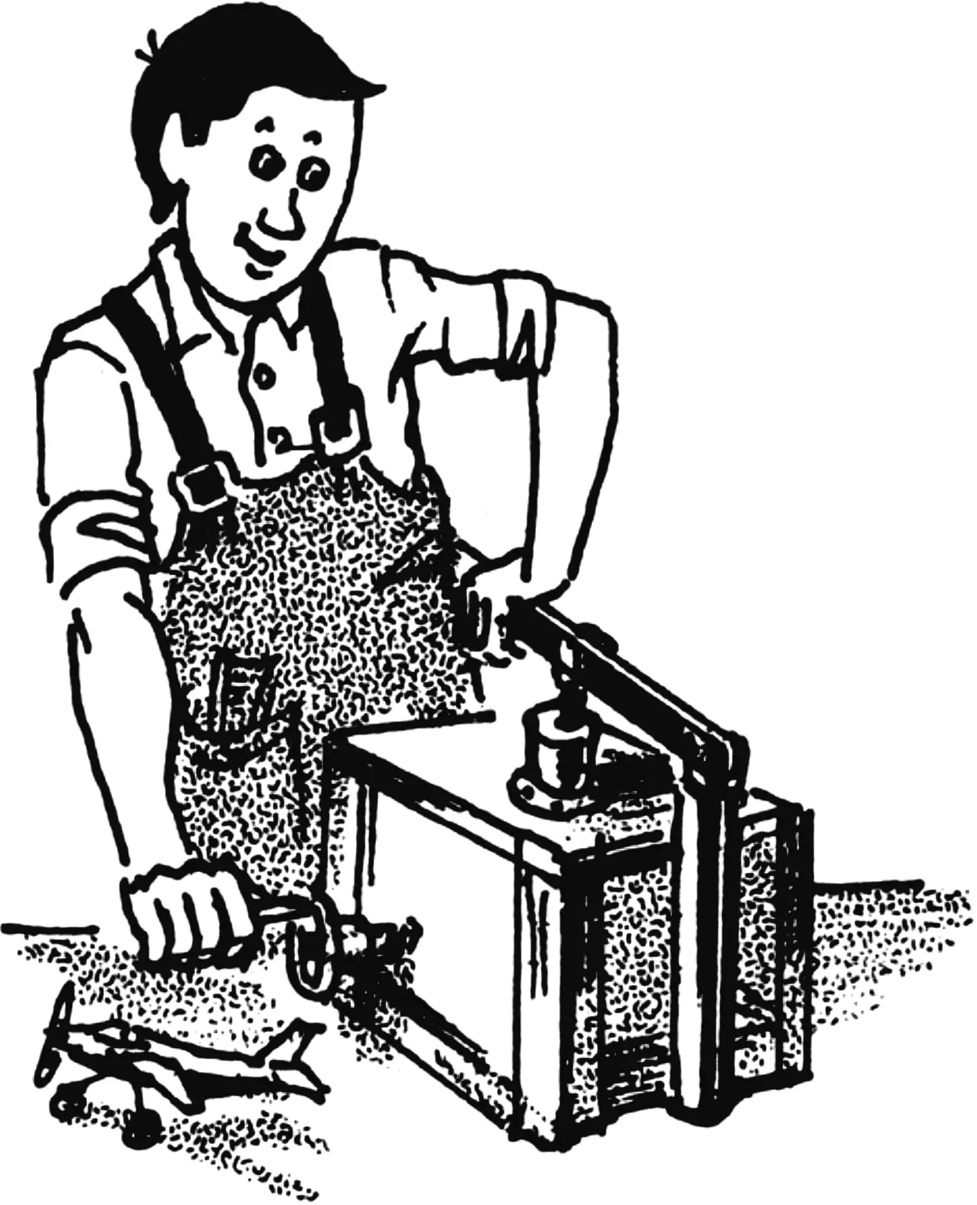
I have subscribed to the “Modelist-Konstruktor” magazine since 1985 and have never regretted it. I read everything: from the first page to the last. It is a very useful and interesting publication. And although times are hard now and the magazine is not exactly cheap, I will continue to subscribe, because I believe the value of the magazine is higher than its price.
The magazine regularly publishes, in sufficient volume, drawings of armored vehicles, aircraft, and automobiles. But, unfortunately, the technology of making scale-model copies from them, as well as the designs of equipment and fixtures without which their creation is difficult, is described rather infrequently.
Several years ago, one issue of “Modelist-Konstruktor” published a description of a device that could be used to cast plastic parts for models. I liked the idea: taking it as a basis, I made my own version of an injection machine, which I offer to the readers of the magazine.
The injection machine consists of three parts: the base; the upper part, which includes the melting chamber with a press; and the lower part — represented by half-molds and a mechanism for closing/opening them.
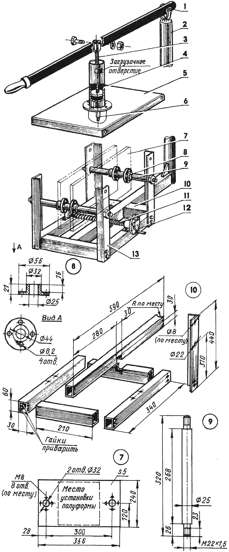
1 — lever (steel strip 25×4); 2 — lever support (cardan shaft from a passenger car); 3 — rod with piston; 4 — melting chamber; 5 — cover (steel angle No. 2.5 and board s20); 6 — die; 7 — movable plate (St3, sheet s5, 2 pcs.); 8 — slider (St3, 4 pcs.); 9 — guide (2 pcs.); 10 — base (steel tube 60×30); 11 — screw (from a car jack); 12 — handwheel with handle (from a milling machine); 13 — upright (steel, angle 36×36, 4 pcs.)
Some dimensions are missing on the injection machine drawings — for example, the height of the melting chamber, its diameter, and others. I did not mark them deliberately: in one case I used ready-made parts (of course, modified), in another — because they can be varied depending on the materials available.
The base frame is welded from rectangular tubes 60×30 mm. The middle element is made longer — a lever support, made from a passenger car cardan shaft, is welded to the end of its extension. The joint is reinforced with a gusset plate. Uprights made from 36×36 mm angle steel are attached to the outside of the base at the corners. A cover is mounted on top of the uprights, and the melting chamber is secured to it. The cover frame is made from 25×25 mm steel angle, and the deck is better made from 2—3 mm steel sheet (mine is still wooden). The cover is attached to the uprights with M8 bolts. The melting chamber is mounted on the cover with some play (with bolts whose nuts are not fully tightened, through enlarged holes). This is necessary so that when the half-molds are closed, the die is centered in the sprue system. After that, the nuts are tightened fully.
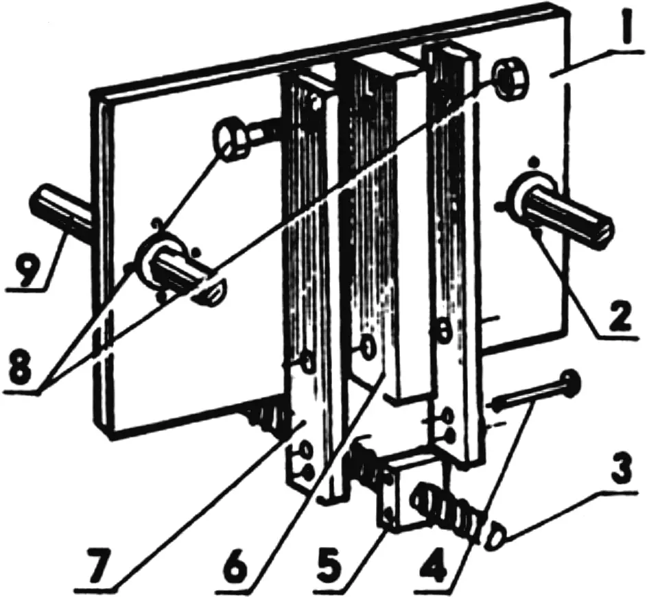
1 — movable plate; 2 — slider; 3 — screw; 4 — steel rivet (4 pcs.); 5 — lead nut (from a car jack, 2 pcs.); 6 — bracket (St3, thickness — to match the lead nut, 2 pcs.); 7 — link (St3, sheet s8, 4 pcs.); 8 — M10 bolt with nut (6 pcs.); 9 — guide (from the rod of the “Niva” combine harvester hydraulic cylinder, 2 pcs.)
The melting chamber is made from the hydraulic cylinder of the “Niva” combine harvester. Looking ahead, I will note that the guides for the movable plates are made from the rod of this hydraulic cylinder. The melting chamber also serves as the injection cylinder. The piston and rod were also taken from the mentioned machine, only the rod diameter was reduced. A lever is attached to the piston rod to create the required pressure.
A die is built into the bottom of the melting chamber cylinder, through which molten plastic under pressure enters the mold. The mold consists of two half-molds, each of which is attached to its own movable plate. The plates are made from 5 mm steel sheet. They are part of the half-mold closing/opening mechanism and are suspended on two common guides on the base uprights. To avoid plate misalignment during movement, two sliders are attached to each plate. The plates are moved by a special screw through lead nuts (these parts are from a car jack) attached to the lower edge of the plates. In my case they are connected by links, but it is simpler to weld the nuts to the plates. The screw has right-hand threads on one half and left-hand threads on the other. Its ends are secured in plain bearings whose housings are attached to the base. The screw is rotated by a handwheel with a handle.
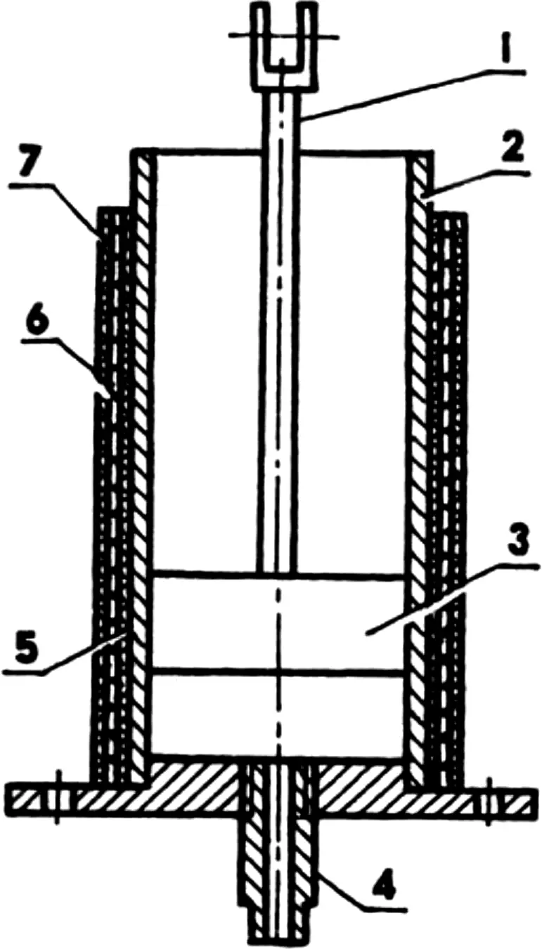
1 — rod; 2 — chamber-cylinder (from the “Niva” combine harvester hydraulic cylinder); 3 — piston; 4 — die (St3, rod Ø10); 5 — electrical insulation layer (mica); 6 — coil; 7 — heat-resistant coating (silicate glue with asbestos chips, sheet asbestos)
The technology for making plastic parts is as follows. The piston is raised to the uppermost position. Pre-crushed polystyrene (or another type of plastic) is poured through the loading hole into the melting chamber cylinder and heated to the melting temperature (for polystyrene, about 180°C). Before pouring, the mold must be prepared — lubricated with silicone grease (it is better to use the kind sold in an aerosol can). Readiness of the plastic for pouring is determined by the beginning of its flow from the die. By this time, the plates must be brought together by rotating the screw and the mold halves joined. At the same time, the upper part of the sprue channel must be pressed tightly against the die. Then the melt is sharply injected into the mold under pressure created by the lever and piston. After the plastic has hardened, the mold is opened by rotating the screw in the opposite direction and the finished casting is removed from it.
The injection machine makes it possible to obtain parts that are practically equal in quality to industrial ones.
“Modelist-Konstruktor” No. 11’2002, V. YATSURA
Recommend to read
 WIELOOSOBOWE
I'm a longtime subscriber of your magazine, he was engaged in shipbuilding and automodelismo. In many everyday situations, helped me publish "rubric Club home of the masters". ... GIVE A BELT COVER…
For the case when screw cap cans, as they say, stuck and does not open, use a simple device made of a wooden block and the old lap belt. Guides buckle do not necessarily, but to nail the...
