The rotation of the motor to the saw blade is passed a single a chain and two belt and pulley. The first belt drive connecting the intermediate pulleys, in addition, serves to connect the working motor to the drive instead of a clutch. This operation is performed by simple deflection of the connecting rod roller-tensioner under the influence of the spring. The primary shaft is mounted in two bearing supports, rotates continuously. The axis of the pendulum though is in the bearings, is rotated only when moving up or down, and double pulley, seated at her spinning in its own bearings independently of the shaft. A circular saw blade mounted on a driven shaft with two faceplates and a nut with left-hand thread. Drive belt tension can be adjusted by moving the supports along the beams of the shaft of the pendulum using the control mechanism.
Frame saws are assembled from a steel angle bolted and then, for greater strength, cooked.In the lower part of the padded cross beams, spars and plates for the engine mounts and bearings, intermediate shafts. On top there are brackets, on which is placed a tank of gas. Finally it is fixed on the frame by two steel tapes. To longitudinal beams of the bottom frame is welded tube into which is inserted the axle shaft of the wheels.
Pendulum saw (engine, piping and wiring of the conditional ie are shown):
1 —disc circular saw (Ø480); 2 — pulley driven (Ø 76); 3’—arm (motorcycle); 4 — a protective casing (STZ, the sheet sl); 5 — beam pendulum (STZ, 50 channel); 6 — recoil mechanism (STZ, strip 25×5); 7 — stopper mechanism of a tension of the intermediate belt (STZ, strip 25×3); 8 — frame; 9 — tensioner pulley (with a/C car); 10 — exhaust pipe; 11 —fuel tank; 12 — tape fastening to the tank (STZ, strip 25x 1,5, 2); 13 — engine PD-8; 14 — engine mounts (steel 45, the sheet s8); 15 — rod of the tensioner (STZ, pipe 40x25x2); 16 — spring; 17 — front (STZ, area 32x32x4,4 pieces); 18, 34 — struts (STZ, strip 25×3, 4 valves); 19 — bearing Adjuster (STZ, channel 50); 20 — return spring; 21 — stopper log (STZ, area 20x20x3, 3). 22 — carrier (STZ pipe, 40x40x5); 23 — the bearing support axis of the pendulum (from agricultural equipment); 24 — driven sprocket (z=20); 25 — support bearing from the intermediate shaft (from agricultural equipment); 26 — muffler (motorcycle Voskhod, shortened and modified); 27 — the support bearing of the connecting rod; 28 — intermediate shaft (from agricultural equipment); 29 — pulley presenter (Ø117.); 30 — pulley, start the engine (Ø250, from agricultural machinery); 31 —double pulley (Ø117., C/x equipment, modified); 32 frame reception (STZ, area 40x25x3); 33 loop retainer (STZ, Ø8 rod); 35 — the wheel (from agricultural equipment); 36 — housing of the system of forced cooling of the engine (from the engine T-200); 37 — the leading sprocket (z=10); 38 — retaining ring (steel 45, s3); 39, 42— spacers (steel 20, steel 34×1,5); 40 — the axis of the pendulum (from the s/s technique, 030); 41 —bearing 180206 (2); 43 — jumper (STZ, 50 channel, 2); 44 — bracket Adjuster (STZ, angle 50x50x5, 2); 45 — Bush (Vs welded); 46 — mounting brackets to the pendulum axis (STZ, area 32x32x4, 2); 47 — bolt M8 (4 PCs); 48 — faceplate; 49 — yoke mechanism belt tension (STZ, strip 25×5, 2 PCs); 50 — nodes bearing driven shaft; 51 — belt drive 0 — 2000; 52 — bolt M8 (2 PCs); 53 — clip (STZ, strip 25×5); 54 — bolt M10 (4 PCs); 55 a driven shaft; 56 —lever “gas”.
Frame (all parts are made of Vs):
1 — cross member (area 45x45x4, 2); 2,7 — stands (area 36x36x4); 3 — stand support axis of the pendulum (channel 50, 2); 4 — the stand supports the intermediate shaft (tube 40x40x4, L200); 5, 8, 9 — cross-member upper (area 36x36x4); 6 — cosina (36x36x4, 2); 10 — mount gas tank (area 36x36x4, LЗОО); 11 — spars engine mounts (area 70x70x7, L400); 12 — emphasis of the exhaust pipe (area 36x36x4); 13 — front stop (area 36x36x4, L250, 2); 14 — beam of fastening of a support roller tensioner (area 36x36x4); 15 — beam engine mounts (area 36x36x4); 16 — longitudinal beam (area 45x45x4,2 PCs.).
Kinematics:
1 — engine; 2 — pulley (Ø117.); 3 — ball bearings 11206; 4 — pulley start engine; 5 — tensioner; 6,9 — straps; 7, 14, 20 — 180206 ball bearing; 8 — a pulley of the dual (Ø117.); 10 — a pulley driven (Ø76); 11 —disc circular saw; 12 — pendulum; 13 — axis of the pendulum; 15 — rod; 16 — intermediate shaft; 17 — sprocket (z=20); 18 chain; 19 — sprocket (z=10).
Carrier is the sequel to the frame, so as rigidly connected with it two pairs of struts and braces. It is made of tubes of rectangular cross section and serves to move the machine, and as its front support. The cage is welded to each frame with three stoppers, designed to hold the logs against rotation, and bearing return mechanism of the pendulum.
The pendulum consists of two parallel beams, located at a distance of 32 mm from each other and interconnected by crosspieces. On one end there is mounted a closed housing the saw blade and the other the pendulum attached by two corners and bolts directly to the axle. In an unusable state (when the drive is disabled) the pendulum is at a certain angle to the horizontal so that the disk does not interfere with the flow of the logs. The rise of the pendulum after the next cutting and hold it in this position produced a return mechanism, comprising: adjustable support, guide, spring, two brackets connected to the beams of the pendulum, and the sleeve is pivotally suspended between the brackets. The motion of the pendulum guide is free to slide in the sleeve. The spring is chosen so that in the course of working she especially did not interfere with the operator’s force, but reliably return the weight to the top, i.e. the source position. The protective cover riveted construction made of sheet steel. To hold the pendulum casing is equipped with three lanes, brackets secured to the beam by bolts.
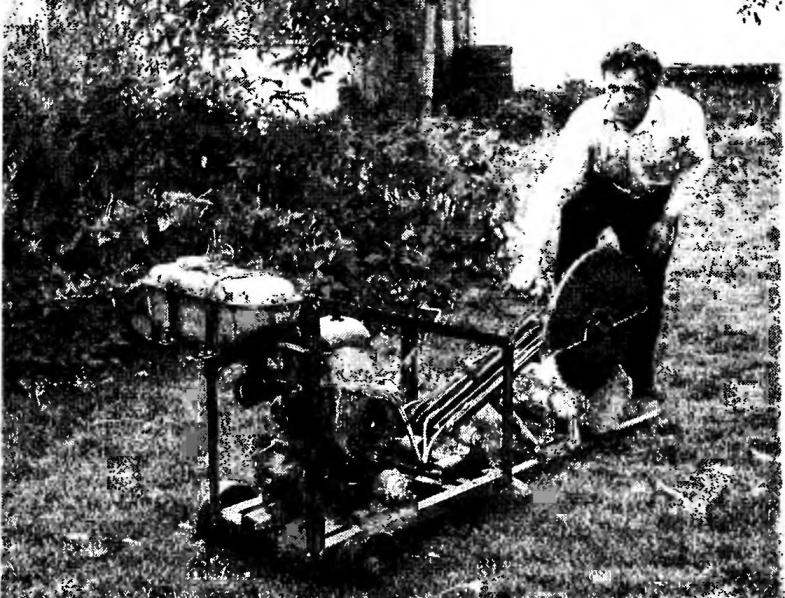
Technology of work with a saw of this design is quite simple. First, the operator makes sure that the tensioner intermediate belt and the pendulum is raised (intermediate belt loose, grip it with the pulleys is missing). Then he puts in a reception frame of the log to be sawed on the wood, and starts the engine. Removes the stopper from the tensioner and lowering the roller, pull belt, thereby connecting to each other intermediate the pulleys. The saw blade begins to rotate. Press the arm of the pendulum, the operator lowers the saw and cuts a block of wood. Thus, depending on the density and structure of wood regulates the rpm of the drive lever “gas”. In the future, it all operations are performed in reverse order until the clutch release, which is necessary in order to ensure the safety of the operator when subsequent submission of the logs.
The idea of pendulum saw E. Kulikova will be incomplete if not to say that it faithfully serves the owner and his neighbors for about ten years.
V. KUDRIN
Recommend to read Mil Mi-28 An experimental model of anti-tank combat helicopter Mi-28 first flew on 10 November 1982. Was built four prototype — they completed the full cycle of state tests. Rotor... BLIZGAREVA Many Housewives prefer to dry clothes in the street, and dries faster, takes on a special flavor. Here only each time with a rope hitch: to tie, to untie, and the wind so wound posted...