PLOW MOTOLIBERTY

PLOW MOTOLIBERTYNow an extremely acute problem of processing individual land plots. The horse would plough the field! But where are these loshadke? Motor-block to replace? Well, if you believe the advertising avenues, such a solution seems quite reasonable. But in fact, alas, it turns out that not all can praise MB. Not to be unfounded, I will refer to the neighbors of tests of MTZ-0.5 plowing. So: we have a heavy soil (clay mostly). They advertised this walk-behind… takes 5-7 cm in depth. And this is with the suspended cargo, and special plough-wheels. Crop after such “processing” of the soil, as they say, never gonna happen.

Looks very attractive idea to use as a “draft force” plow “anchor” windlass. But there are some drawbacks. The plow you have to manually move (and he is no slouch) to the beginning of the furrow. It requires at least two adults. And even better to work here three: the two return to the plough, and the third for the winch. However, for individual areas such labor organization seems wasteful. But not whether to do the opposite: to set to the plow, the winch tightens itself and arable weapon to still, buried in the ground to anchor? After recently having a mass of 3 kg, to transfer to a new beginning of the furrow and securely there to fit even the student-a first grader.
 
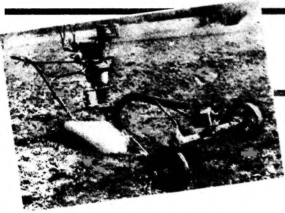
I then took the motor from a chainsaw “Friendship 4”, two-stage reducer from augers M-1 ratios I=1:10, I=1:20, and “neutral”. Strengthened on the output shaft of drum length of steel water-gas supply pipe and a 2-mm steel cheeks. Wounded on the last 70 meters 3.5-mm steel cable and the resulting Assembly was mounted vertically on an ordinary horse odnoimennyi the plow. And the bottom part of the drum shaft inserted into the bearing of the cross tucked under the hands of the driveline. Then the bracket from a steel angle secured the bearing on the blade of the plow.
Subsequently, to protect the cable from dropping from the drum when the load is removed, provided special spring-loaded clamping drum (see illustration). It also managed to produce a segment of steel water-gas supply pipe with lugs-plugs on both ends.
 
Almost collected the power unit is secured in the upper part of the brackets the struts from 10mm steel rod and tightened the nuts on the arms (chepiga) of the plow. Thus there was a real possibility of position adjustment Assembly forward and backward. And it truly should final “fine-tuning” of samokleyki of rope on the drum.
 
A special thrust locks the unit upright, not allowing the shaft end of the drum out of the bearing. It is located directly behind the drum.
 
TECHNICAL DATA MOTOLIBERTY-PLOWMAN
 
The layout of the MLP (without the anchor)
 
The layout of the MLP (without the anchor):
1 — the plough-based (one-horse with the beam), 2 — drum pressure, 3 — bearing Assembly with bracket, 4 — reel cabled, 5 gear, two-stage with “neutral” (augers M-1), 6 — bracket kosina (2 PCs), 7 — arm “gas”, 8 — button ignition, a 9 — engine (on chainsaws “Friendship-4” upgraded), 10 — fuel tank, 11 — wheel of the field 12 — roller-pull cable guide in a horizontal plane (2), 13 — cable 14 video-guide in a vertical plane (2), 15 — wheel borozdna.


Kinematics motoliberty-plow
 
Kinematics motoliberty-plough:
1 — motor, 2 — gearbox, 3 — reel cabled, 4 — bearing Assembly (from the cross-piece driveline of the car GAZ-53A), 5 — field wheel, 6 — wheel borozdna, 7 — anchor, 8 — single-horse plough with the frame sides.


Option homemade plow-basics of MLP (mount the power unit conventionally not shown)
 
Option a homemade plow-basics of MLP (mount the power unit is not shown):
1 — wheel borozdna welded (5 mm St3, rim diameter 280 mm), 2 — roller guide rope in a vertical plane (in the cage, 2 pieces), 3 — a cable (a 3.5 mm steel rope with a length of 70 m), 4 — wheel field welded (2 mm St3, rim diameter 150 mm), 5 — the beam (a segment of pipe seamless steel 40×4), 6 — field-unit Board (6 mm ST5), 7 — heel-slide (Steel IIIX15), 8 — blade (cylindrical surface, a 3 mm St3), 9 — shingles (7-mm Steel SHKH15), 10 — roller-pull cable guide in the horizontal plane (in the cage, 2 pieces), 11 — bracket “front”, 12 — gusset plate weld (5 mm STZ), 13 — stand (cut from pipe seamless steel 40×4).


Design of a tension cable reel
 
Design cabled drum:
1 — cheek (2 mm St3, 2), 2 — the basis of the drum (156 mm cut pipes 114×4 steel water-gas supply).


Pressure drum
The presser drum:
1 — boss (from 25mm oak Board, 2 PCs.), 2 — the basis of the drum (160 mm a section of pipe 60×3,5 steel water-gas supply).


Anchor (welded construction, the basis — cutting of steel water-gas supply pipes 33,5x4)
Anchor (welded construction based — obrezki steel water-gas supply pipe 33,5×4):
1 — arm, 2 — bar, 3 — point blank-base, 4 — bayonet (2-mm ST5).


Data field for cutting boards (C, d), the blade (e, f to the constraint line i) and the blade (the shape within the y-axis and the lines e, f, g) attached to the blade h. Lines g, h, i are constructed by two points with corresponding x
 
The data field for cutting boards (C, d), the blade (e, f to the constraint line i) and the blade (the shape within the y-axis and the lines e, f, g) attached to the blade h. Lines g, h, i are based on two points with the corresponding abscissa.
 
 
Table scan field of a Board, the blade n of blade (for V. Yakovlev, No. 5,'91)
 
Table scan field of a Board, the blade n of blade (for V. Yakovlev, No. 5,’91).
 
 
The front part of the beam relies on two-wheeled site, which provides for a “regular” of height adjustment (in transverse direction). They were from the same, basic, model of a plow horse. Thanks to a special adjusting device, left (field) wheel had the opportunity to change track. But it was subsequently unnecessary.
 
Right (borozdna) the wheel is mounted on the outer arm with the flat side inside. Well, this is understandable: after all, he will have to constantly RUB against the wall of the furrow when plowing, to plow the whole in the end well – “keep the groove”.
 
In front of the beam is located and the receiving device. It is easy to verify (see Fig.), it serves to guide the wire rope at mid drum at any deviation of the plow from the anchor. Consists of 4 rollers. The rear one above the other with minimal clearance between the flanges to the exhaust cable has been strictly aimed at the middle of the drum. Besides, perpendicular to the axis of the latter, for better samokleyki turns. Adjusted all the upper brackets-Yoshinari, tighten nuts in the holes on the arms (Ichigo) of the plow.
Vertical cylindrical rollers are made of a 100-mm inch scraps of water pipes; they have internal seats for the bearings with the felt seals (bearings protective type). These videos perceive horizontal (lateral) load of the rope. Due to this technical solution, the plough behaves very stable. To the detriment of controllability can even go with the “thrown to proizvolstva” arms. It is necessary only not to forget about the lever “gas”. He is on the right, under the index finger.
 
For easier manageability, it is highly desirable that the plow was connected with the “front end” is not hard, and swivel. Can be limited… even the omnipresent gap. The most important thing is that the plow could deviate by 15 degrees in either direction.
 
On the left handle of the plough (in accordance with the location of the thumb of the operator’s hand during operation) set button ignition switch is turned off. It is necessary for the de-energization of the motor, if, say, he began a sudden uncontrollable increase in the depletion mixture (emptying the tank). In this case the wire through the puncture in the rubber plug of the capacitor relates to the last contact, and a button connected to ground.
 
I must say that the possibilities of a home Studio, where he gathered all the versions of the MLP small. Yes and it is located almost 200 km from the field, which had to plow. And therefore, for greater assurance of reliable operation, had to provide at first quite a lot of adjustment points. But then it turned out that after debugging MLP in the field not all of them are required for the further operation of the structure.
 
In particular, it is possible to abandon the standard (and heavy) frame sides, replacing it with homemade. Especially since he is not responsible because
 
special vertical loads. Was extra special adjustment left (field) wheel width — it can be placed close to the beam. Almost never need a “front end” in height and the horizon. Enough experimentally once to debug and fix the latter with the optimal settings.
 
But the engine is a little better to upgrade by installing it instead of the standard carb from the bike. After adjustment of the “small gas” there is located directly on the carb for the engine with auto clutch very important.
 
Now a few comments about the anchor. Advisable to carry a shovel with T-handle from a pipe with a bayonet with a width of 260 mm and height of 200 mm from 2 mm steel sheet, bent to the /-shaped (for rigidity). Front — end basis, for which clings to the rope, not giving the anchor to tip over. And it is worth while ploughing, holding the anchor to the ground (for T-shaped handle to hold is not necessary).
 
Work better on long pens — less tired. After all, the main load arises, as when plowing with a plow horse, when moving unit from one furrow to another. The cable should be unwound only at the switched off transfer.
 
V. IGNATOVICH,
Pskov region

Recommend to read

  • ARSENAL HALTARSENAL HALT
    I want to share with readers his small devices, providing added convenience in the organization of the fire in camp during a weekend trek or a trip to his native land. One of the common...
  • KAMA — SLICERKAMA — SLICER
    To prepare starch from potatoes at home I have several years helps... washing machine "Kama". To turn it into productive avometers needed very little improvement. From a round steel...