“ROLL” HAY — STACK

With the growth of livestock per farm farms there was a need of increasing the food supply. Forage – a very laborious process, requiring great effort and fine days weather loosens it a little. Manually, the old fashioned way with a scythe and a rake, with this task to cope became more difficult. Meanwhile, in private households gradually began to appear on trucks, tractors. It took them various agricultural implements, trailers and ancillaries. In particular, hay began to use balers. Now hay pressed in rolls of approximately 200 – 300 kg. They have to be transported from the field to the storage place. But try to raise the weight and throw in the truck or even lift on the truck tractor! So I got the idea to make the so-called tractor lift coils – rear unit operating from the tractor.
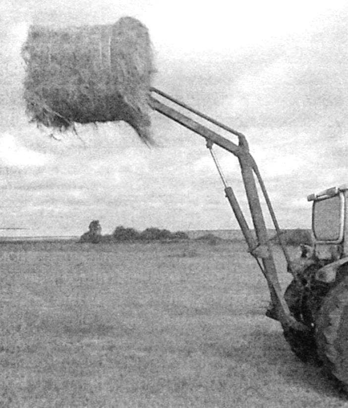
 
Last year this idea was implemented. Turned out, in my opinion (and neighbors too), simple and very convenient to work with forklift. The main parts in it – the grip fork, a mast, a boom and thrust, the base of Yes, a power cylinder, which, however, he did not do. Of course, I had to make from what was available or came to hand, mostly in a scrap yard.
 
The main part of the mechanism – mast built from the pusher bar (“led”) dozer blade tractor DT-75. It was a thick-walled box-beam cross-section 140×120 mm longer than 3500 mm. Cut it to the desired length of 2007 mm. I was lucky, having no such pipe, had to weld it from the channels or angles.
Under the mast base – horizontal support took a tube of rectangular cross section 120×100 mm length 800 mm – the size of the tractor. With both ends set of plugs with pins -they are necessary to connect the base with the linkage.
 
Welded connection of the mast reinforced with support gussets, to avoid fracture of this place when lifting a load.
 
Scheme lift
 
Diagram of the lift:
 
1 – fork; 2 – copy link (Ø50); 3 – arrow (100x100x4); 4 – mast (140x120x6); 5 – the main attraction (40x40x4); 6 – beam base (120x 100×4); 7 – odusina (60x60x3); 8 – power cylinder; a z – pins of the shafts and bases

 
The base of the mast and copy thrust
 
The base of the mast and pull gauge
 
Fork. On the main I-beam mount jibs and copy thrust
 
Fork clamps. On the main I-beam mount jibs and copy thrust
 
To the mast needed more boom. Her used wheel balancer support from harrow LDH-10 profile sizes 100×100 mm, which made the procurement of such arrows with a length of 1250 mm. Now it is time to put both parts in the top. To do this to the walls at the end of the boom welded two plates with holes for the pin. To the main mast welded the bushing under the same pin. Combining the boom and mast received one folding detail, is composed of two parts.
 
Hydraulic cylinder for lifting the boom took from the front loader PKU-08. It weighs about 30 lbs. To my lifts, it was important to center distance was not less than 940 mm, and the piston could move up to 630 mm.
For the manufacture of the forklift used part trailed cultivator KPS-4 and the axle shaft GAZ-53. From trimming the trailer has been the basis of capture – the beam cross-section 110×70 mm and a length of 500 mm. Two axles with a diameter of 40 mm and a length of 78 mm went to the teeth. For articulation with traction and arrow cut out lugs with holes for cotter pins. All connections of these parts to each other – welded. In addition, the metal band further strengthened the teeth with the base, to avoid their bending under the weight of the bales of hay.
 
The unit of connection of the thrust boom and the forklift
 
The connection node of the thrust boom and the forklift:
 
1 – tooth capture; 2 – panel; 3 – bar linkage; 4.7 – cotter pin; 5 – copy thrust; 6 – bolt and 8 – lug boom; 9 – Foundation

 
Mast base
 
The mast base:
 
1 – mast; 2 – odusina; 3 – beam base; 4 – plug; 5 – pin

 
Still had to do to capture during raising and lowering of the boom constantly kept in a horizontal position. For this was cut thick-walled tube with a length of 1350 mm and welded to both ends of its lugs. Turned out “copy” arrow thrust (parallel to the arrow from the top of the mast to capture). For mounting the thrust had to be welded to the end of the mast eyelets – two metal plates with a thickness of 8 mm and a height of 23 mm.
 
The lower end of the pull rod bent at a slight angle and connected to the base of the forklift. This is done so in full boom grip was slightly down from the horizontal position. This gave the opportunity to put the roll in the car body, trailer, lying, and standing.
From one thick-walled square tubes size 40×40 mm made main propulsion with a length of 2100 mm. She had to pass from the top of the mast to the bracket Central thrust of the tractor hitch. Therefore, the upper end again, welded lugs, and the bottom is a hinge with fastening screw. Such a long pull helped to increase the stroke of the mast.
 
Tractor lift coils, rear unit, powered by tractor
 
Tractor lift coils, rear unit, powered by the tractor
 
 
The “carrier” (arrow) dozer blade tractor DT-75. This was used for the manufacture of a mast
 
Balancer (shown by arrow) of the wheel supports of the cultivator LDG-10. The same was applied for the production of
 
The rocker (arrow) of the wheel supports of the cultivator LDG-10. The same was applied for the manufacture of
 
Acting with the tractor, got the opportunity by working long thrust to tilt the mast of the lift at a certain angle as needed, and using the power cylinder to control the boom. The parallelogram formed by the arrow, copy thrust, and both sides of their attachment, allows and under load to keep the forks in a horizontal position. In the future, after the capture of male have the opportunity to make and insert inside the arrow detachable extension cable with a hook, which will allow to raise not only the rolls of hay, but various other cargo weighing up to 700 kg.
 
In conclusion, I should note that the labor spent by me on making this lift is quite justified. The mechanism is well proven to work, allowing you to minimize the time required for the harvesting of hay at our farm.
 
N. GOLOVANOV, Nizhny Novgorod region.

Recommend to read

  • PLOWMAN SLOPING FIELDSPLOWMAN SLOPING FIELDS
    Now, as strengthening the material-technical base of agriculture, in all growth, the challenge to improve its efficiency, to improve all quality indicators. This requires... care about...
  • The MiG-3The MiG-3
    The fighter I-200 was developed from November 1939 under the leadership of H. H. Polikarpov, and then A. I. Mikoyan and M. I. Gurevich. The first flight took place on 5 April 1940 the...