TILLERS SIBIRYAK

MOTOBLOCK SIBIRYAKSimplicity in manufacture and maintenance, reliability, versatility— these are the qualities that I wanted to achieve by producing tillers. Now, after two years of operation at the farm, I can say that the goal is achieved: the machine has become an indispensable helper with a set of attachments walk-behind tractor is used For plowing, cultivating, hilling, harrowing, and in winter — to clear Paths of Snow. In the coupler with a single axle cart with a wooden body and driver’s seat, turns the self-propelled chassis carrying up to 200 kg.
Walking tractor frame is welded from steel pipes square and rectangular cross section. Her spars—two-meter segment of a cross section of 42 X 42 X 3 mm with their ends welded to the cross beams with a length of 230 mm and a cross section 30X30X3 mm. Frame is reinforced with a Central crossbar. Beside it, under the spars — welded two of the bridge supports of the segments of the rectangular pipe 45 X 20 X 3 mm.
 
Support the engine and the fuel tank is bent from thick steel strip U-shaped bracket with a width of 40 mm,
 
Fig. 1. Motoblock
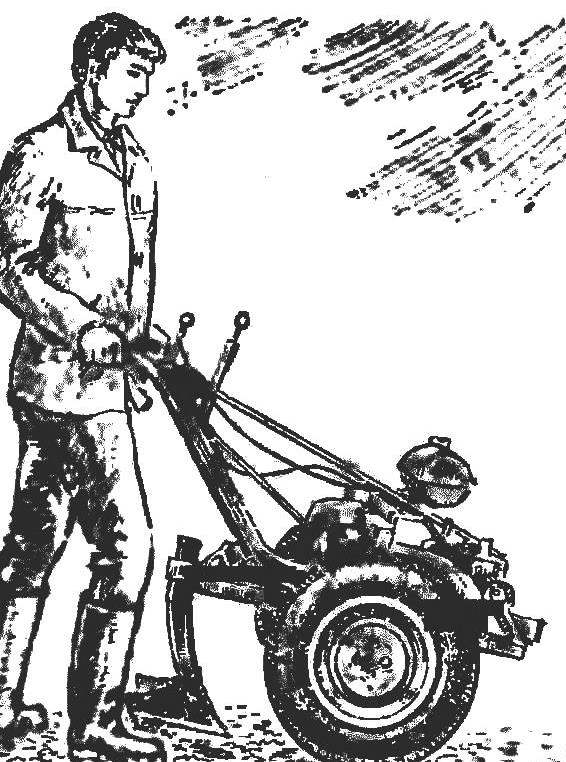
Fig. 1. Motoblock “Siberian-3”.

 
As the power unit used engine chainsaw “Ural MP-5” capacity-5 liters “. Connected to the crankcase bevel gear chainsaw “Friendship”. Through the application installed on the output shaft of the gearbox sprocket Z1 {16 teeth) and chain (pitch 12,7 mm) Torque is transmitted to the sprocket 1-2 input shaft to the gearbox from the motor scooter “Vyatka”.
 
This arrangement of the units may seem unnecessarily complicated. Indeed, to use the engine of the scooter Assembly from the box would be easier, but I chose this option based on the availability of my parts and assemblies.
 
Fig. 2. Kinematics of two-wheel tractor
1, the bearing axle No. 205. 2 — axle shaft 3 — Noah output shaft of the gearbox of the bridge. 4 — reducer axle, 5 — axle sprocket , 6 — chain, 7 — sprocket transmission output shaft , 8 gearbox . 9 — sprocket input shaft nerobkie, 10 chain 11 sprocket gear motor , 12 is a conical reducer from a chainsaw “Friendship” 13 — engine.
 
Since the engine is pretty high rpm and three assists in the box is not enough, the possibility of replacing the input sprocket gear to obtain the necessary range of speeds for ploughing and transport operations. When installing a sprocket with 36 teeth received transmission with high torque, with 16 teeth —more speed, providing the maximum speed of the tillers to 20 km/h.
 
So when replacing a large sprocket to the small chain does not SAG in the transmission includes a tensioning sprocket, the axis of which can move in the groove of the spar.
 
Figure 3. Frame walking tractor
Figure 3. Frame walk-behind:
1 — cross salka, tube 30X30X3 mm. 2 — spar, pipe 42X42X3 mm, 3 — Central cross member, the tube 4 mm. 45X20X3 — support bridge, pipe 45X20X3 we. 5 is a vertical guide rail hook bracket, pipe 42X20X3 mm, 6 ladder mount tow bracket, steel rod d10 mm,7 — longitudinal beam tow bracket, pipe 42X42X3 mm,8 — groove fastening axis of the idler sprocket.

 
The output gearbox sprocket (15 teeth) is connected by a chain (pitch 19,05 mm) with a sprocket (11 teeth) the rear gear from a cargo scooter, TGA-20 “Moore way”.
 
To provide a rigid axle suspension of the wheels, I had to make a number of modifications. Of the steel rod are machined two axis, and the bearing is attached to the neck size, ensuring Posada) inner ring of the bearing with an interference fit. This is to prevent axial displacement of the rod Then at one of the ends of each axle is welded to a splined coupler, and the other, after the installation of the ring under the protective seal, wheel hub. These items can be used from the rod “Ant”
 
Fig. 4. The mounting bracket of the engine.
 
Bearing housing axle shafts are made from thick-walled steel pipe outer diameter not less than 60 mm and a length of 220 mm. With one; of the parties rastaquouere hole
 
d 52 mm intended for TLD) ball bearing No. 205, and the groove for the retaining snap ring to them. Prevents bearing) from dirt and keep them grease the o-ring from a thick sheet of felt, is installed between two steel plates. The other end of the housing is welded in the flange, the joining bolts to the axle housing. Thus, the gear unit housings axle Assembly forms a rigid bridge. It is firmly attached to the frame with four bolts passed through Apertures of the side members of the frame, and two spring u-bolt clamping the ends of the axle housings to the supporting brackets.
 
On the heels of the hubs of the axles are mounted the wheels of the scooter. Their drives ended, which allows you to change track: 500 mm for processing the rows and 650 mm for transport works.
 
R and p. 5. Axle shaft Assembly
R and S. 5. Axle shaft Assembly
 
To increase grip possible with easy lugs, made of end-grain Elevator of combine chain with remote scrapers. The chain is connected in ring size of the outer diameter at half-mast wheels. Placing it in the middle of the treadmill, pump up the tire — lugs firmly sit on the tire.
 
All control units of the motor-block is arranged on the steering wheel — two bent, respectively, an increase of driver steel tube ø 22-25 mm, bolted to the frame rails. Here are the throttle of the carburetor, clutch, gearshift, turn on the reverse bridge, and a button to stop the engine.
 
To reduce vibration loads all the units of the power plant, except for the drive axle, are mounted on frame through rubber gasket.
 
Attachments can be quite varied, based on the specific purpose and conditions, but the traction characteristics of the tillers make it possible to apply odnoimennoy plow, cultivators and Hillers in two rows, zu-
bowww a harrow with a width of 80 cm and the blade width of about 70 cm.
 
Fig. 6. Installing the rear axle
Fig. 6. Installation of the rear axle;
1 — longitudinal girder frame, 2 —bolt gear case to axle, 3 — standoffs.4 — axle, 5 — bridge bearings,6 — step ladder, 7 — body axis, 8 — flange.

 
For a variety of transport operations tillers connected with a single axle truck. Its welded from steel profiles fixed frame a spacious wooden body, the driver’s seat and turning the coupling device providing vertical stiffness of the connection. Wheels with brake drums (“Ant”) is equipped with mechanical brakes, controlled by pedal from the driver’s seat.
 
I think that the machine has not been exhausted. Work on its improvement continues. For example, I planned to conclude the PTO to use the engine to drive various mounted and trailed implements.

Recommend to read

  • PETLYAKOV PE-2PETLYAKOV PE-2
    Dive bomber PE-2 was developed in OKB V. M. Petlyakov on the basis of previously established experimental twin-engined high-altitude fighter VI-100. The first production PE-2 was...
  • TT-1 Pinto (USA)TT-1 Pinto (USA)
    Double training aircraft "model 51" the firm", Temko aircraft Corporation" developed in 1955 in the framework of the competition announced the U.S. air force on the creation of training...