The appearance of the transformer
Then to wrap coils to completely fill the secondary winding, using the three-phase power multiple-strand cable consisting of three wires d 6-8 mm and one finer. It can withstand big current, has reliable insulation, due to its flexibility, able to execute tight winding without prior disassembly of the unit. Only go about 25 m of this cable. It can be replaced and a wire of smaller cross section, adding cores at the winding half.
The work together to perform one puts the coils, and the other stretches the wire.
The terminals to the terminals of the secondary windings are fabricated from copper tube d10—12 mm and a length of 30-40 mm. on the one hand asclepia her pochivshaya plate drill hole d10 mm, and with the other carefully insert the stripped wires, and crimp them by light hammer blows, and then to improve contact make surface of the tube notches Kern.
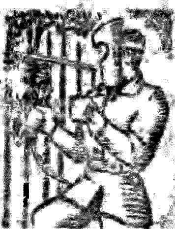
Electrode holder :
1 — electrode, 2 — spring, 3 — pipe, 4 — rubber hose, 5 — WINNT and nut M8 6 cable .
With the panel located at the top of the transformer, remove the regular screws with nuts M6 and replace them with two new threaded M10 (preferably copper) — they will be connected to the terminals of the secondary winding.
For the conclusions of the primary winding manufacture the additional cost of the PCB thickness of 3 mm and attach it to the transformer, as shown in the figure. Pre-drill it 10отверстий d of 6 mm and insert them infused with two M6 nuts and washers. If the device will be powered by 220 V, the two extreme connect the windings in parallel, and the average connect them in series (see wiring diagram).
Even better, the device operates from a network 380 V. In this case, all primary windings connect in series — first, two extreme, and then average. The extreme conclusions of the windings connect to a common terminal, and the other two to the terminal “Cutting”. The average winding branches going respectively to the terminals “1”,”2″, “3” etc secondary winding performs the function of additional inductive resistance in the circuit to the extreme, reducing the voltage and current in vtorichnoi winding.
The electrode holder (see Fig.) made of pipe 3/4″ length-250 mm on both sides of the pipe at a distance of 40 mm and 30 mm from its ends saw a hacksaw notches with a depth of half the diameter. And the electrode can be clamped to the holder, weld to the pipe over a larger notch cut steel wire Ø6 mm. From the opposite side, drill a hole d of 8.2 mm and with copper terminals and screw with M8 nut connect the holder segment of the same cable, which is wound the secondary winding. On top of the pipe wear rubber or nylon hose with the appropriate inner diameter.
Electric connection diagram of the windings of the transformer for 380V
The device connects to the network via switch wires at least 1.5 mm3 — one to the terminal marked “Common.”, and the other to one of the terminals “1” — “8” (depending on the welding current). The biggest shock will be when connected to the terminal “Cutting”.
The current in the primary winding of the transformer does not exceed 25, And the secondary current changes from 60 to 120 A.
Don’t forget that welding machine is designed to perform a relatively small amount of work. Therefore, after using 19-15 electrodes d3 mm it is necessary to cool.
Respectively, with the electrodes d4 mm time of continuous operation of the installation is hiding be reduced even more. But with electrodes d 2 mm it is possible to act without forced breaks (heating temperature of the transformer does not exceed 70-80°).
In the “Cutting” welding machine heats up faster, and therefore to “rest” in this case he needs more. You can cut almost any metal used in the home thickness.
When changing from one welding mode to another do not forget to disable the network switch.
Recommend to read THE PUMP WILL NOT BE LOST I am fond of Cycling. Repeatedly convinced of the unreliability of fastening of the pump on the frame. Making a simple revision, I solved this problem once and for all. Perhaps my... THE BATTERY IN THE FRAME When equipped with a headlight of a Bicycle "Salyut" there is no need to manufacture special container for batteries. It can be hidden directly in the frame, pre-SPAW three elements 343...  To spend water and sewer, to do cages for Pets and birds, beautiful flower stands and many other useful things in the economy will help arc welder made from readily available parts and materials. With electrodes up to 4 mm, they can be welded, the metal thickness of 1-20 mm. Installation (see Fig.) operates from AC mains with voltage of 220 or 330 In
