TRACTOR “WORLD ON A STRING”

THE TRACTOR

To make myself a mini-tractor (MT) is a dream of many. But they sometimes stop because of the difficulties in acquiring scarce nowadays powertrains, gearboxes with the right gear ratio, differential gear and other parts. Other (basic this beginners homebrew) deterred by the complexity of intricate drawings and manufacturing technology design. A longtime subscriber of our magazine, the author of a number of original designs of small tools V. Boldyshev offers not to despair and peculiar to each natural nous braver to do things. How! Technology, which sometimes intuitively come to many of the homebrew, collecting in a single structure existing units and details “at the place of installation”, doing virtually no daunting drawings. A “deficit” around, taking advantage of opportunities Vtorchermet… or lowly of the landfill, which sometimes careless business executives charged fuses good.
As a rule, we each wanted to make with his own hands his mini-tractor (MT) there is an inherent “material base”. Most often it is some old motorcycle or scooter and a couple of the other nodes, it would seem, has its obsolete, decommissioned equipment. It is highly desirable that among the latter was the main^ transmission with reverse gear (say, from motorized SZA), steering column (GAZ-51) as the leading — front of the tractor (say, from T-25 “vladimirets”), And it does not matter if the tires last is damaged: cut or torn with a metal cord. After all, they will have to work with the air pressure in their cells 2.4—2.6 atmosphere as before, and 0.5—1.
 
As used in the construction of MT tractor wheels differ in diameter from wheels of the sidecar, to connect them directly with the main transfer is impossible: it threatens to increase the speed of movement of the mini-tractor with a corresponding decrease in developing them traction. Need final drives — for example, the mechanism of movement of the hoist or other equipment.
 
But the homebrew often have to rely on their own strength: to produce the final drives from the fact that in his hands. Appropriate gear can be selected from deposits of Vtorchermet, passing instead of the required details of the corresponding amount of scrap. And sufficient basis of the case for reducer to make out of steel channel and welded thereto the end caps of segments 4-5 mm steel strip found at… the dump.
The approximate value of the ratio of the required gear is easy to determine by dividing the highest rate, which could have a MT with direct connection tractor copes with the main gear at the desired working. In turn, the higher the speed find by calculating the difference in the diameters of the wheels (“staff” that were on the main transmission, and a new tractor) and knowing the speed of motorized SZA.
 
To pick up gear for just such a gear ratio, is not so sure. The gearbox itself may be somewhat lower gear ratio. The rest is chosen on the sprockets that homebrew is easier to change.
So, if you find a suitable two pairs of gears, shafts, bearings housings, go to the manufacture of final drives. Since the latter is absolutely symmetrical relative to each other and to the longitudinal axis of the mini-tractor, we restrict ourselves to the description of only one.
 
Location of units and parts on the front part of the frame
 
The location of the parts and components on the front of the frame:
1 — front wheel (sidecar cover, 2 PCs.), 2 — front fender (from the “truck” scooter, 2 PCs.), 3 front axle, 4 — frame MT, 5 — front panel with Polikom (scooter “Tula 200”), 6 — footrest (2 pieces) 7 clutch lever 8-the hand (Parking) brake, 9 – brake pedal 10, the throttle 11 – instrument panel, 12 — fuel corrector 13 — shift lever, 14 — the steering column (GAZ-51), 15 — steering wheel, 16 — cockpit side window (2 PCs), 17 — cabin, 18 — windscreen (windshield) glass, 19 — cowl gas tank, 20 — hood of the power unit (back of the cowl from the motor scooter “Vyatka—Electron”) and 21 headlamp (2 PCs), 22 — turn signal (2 PCs.)


Kinematic scheme of transmission
 
Kinematic scheme of transmission:
1 – power unit (motor scooter “Vyatka – Electron”), 2 — sprocket z= 22. 3 — wheel front, driven (2 PCs), 4 — star, g=22, 5 — hand (Parking) brake, 6 gear corner (from the farm), 7 — sprocket z=44, a rear wheel 8, the leading (front of the tractor T-25 vladimirets, 2 PCs.), 9 final drive (homemade, 2 pieces), 10 — drum brake (2 PCs), 11 — main gear (motorized cover), 12 — elastic coupling (motorized SZA or homemade, 2 pieces), 13 -sprocket z=22 (from scooter “Vyatka Electron”), 14 — sprocket z = 14 PTO shaft, mounted on bearings, 15 — star, g= 15, 16 — roller idler, 17 — sprocket z= 15, 18 — bearing.


SPECIFICATIONS
 
 
Frame mini-tractor
 
Frame mini-tractor:
1 — the longitudinal members (thick-walled pipe with an outer diameter of 60 mm, 2 pieces), 2 – cross member (area 30X 30 mm for fixing polycarbonate), 3 — channel 100X 60 mm, 4 frame-arc power unit (tube with outer diameter 27 mm).


MT frame Assembly with gears, main gear and I-beam front axle
 
MT frame Assembly with gears, main gear and front axle I-beam:
1 — main gear 2 — installation place the “corner” of the gearbox (PTO), 3 — area (30X 30 mm) for mounting the tension pulley and polycarbonate, 4 — axle clutch pedal, 5 — bracket mounts the rear of the power unit, 6 — place mounting of the bearing shaft of the power unit, 7 — spot reducer steering column, 8 — channel 100X 60 mm, 9 — beam front axle, 10 — bushing, support-rotating unit (2 PCs), 11 — swivel arms (3 PCs.), 12 — rod, 13 — bandwagon (2 PCs), 14 — side reducer (2 PCs), 15 — hub rear wheel (2 PCs.), 16 corner installation wing (2 pairs), 17 — bearing housing PTO. 18 brackets for mounting the base plate of the hinged device (2), 19 — housing-input shaft bearing, side gear (2 pieces), 20 — the bearing housing output shaft side gear (2 PCs.), 21 — plate housing (2 PCs), 22 — parts 70X70 mm mounting side gear (2 pieces).


Front axle
 
Front axle:
1 — front wheel (2 PCs.), 2 — bushing support-rotating unit (2 PCs.), 3 — axis rotation of node (2 PCs), 4 — axis swing of front axle, 5 — swivel arms (3 PCs.), 6 — axles.


Mounting frame of the power unit on the frame MT
 
Mount the frame of the power unit on the frame MT:
1 – panel with Polikom (scooter “Tula 200”), 2 — longeron MT (2 PCs.), 3 — the steering column (from the GAZ-51), 4 — frame of the power unit (motor scooter “Vyatka – Electron” cut across via Polycom). 5 – shneller 100X60 mm MT on the frame, 6 – frame-arc power unit.

 
Cover fuel tank (steel sheet with thickness of 1.5 we)
 
The casing of the fuel tank (steel sheet with thickness of 1.5 we).
 
 
The hood of the engine (rear part of the bonnet from the motor scooter
 
The hood of the engine (rear part of the bonnet from the motor scooter “Vyatka – Electron”
 
 
1. The frame of the truck-trailer Assembly with pole
 
1. The frame of the truck-trailer Assembly with drawbar:
1 — crossbar (section of pipe external diameter of 60 mm and a wall thickness of 5 mm, 3 PCs.), 2 — area 50X 50 mm and length 80 mm (for wooden spars of the bottom of the body, 4 PCs) 3 — bracket (STZ thickness of 5 mm, 2 PCs.), 4 — bracket (STZ thickness of 5 mm, 2 pieces), 5 — longitudinal (pipe external diameter 60 mm and wall thickness of 5 mm, 2 pieces), 6 — bolt M20 with nut (2 PCs.) 7 — riser (area 25X25 mm, 2 pieces), 8 — pole (tube external diameter of 48 mm and a wall thickness of 4.5 mm), 9 — mechanism of the rotary ring (Steel 45).

 
2. Wheel truck-trailer Assembly with suspension
 
2. Wheel truck-trailer Assembly with the suspension:
1 — wheel Assembly (from a boat “Progress”), 2 — strut-absorber, 3 bracket, 4 — bogie frame (trailer), 5 — area 50X50 mm.


3. Wooden base truck-trailer
 
 
3. Wooden base truck-trailer:
1 — side panel (rack 80X25 mm, 2 PCs.), 2 — spar (beam 80X40 mm, 2 pieces), 3 — cross bar (a bar 95X40 mm, 4 PCs.).


4. Rear and side walls of the truck-trailer
 
4. Rear and side walls of the truck-trailer:
1 – loop lock, 2 -metal trim boards (tin), 3 — hinge side, 4 — wood paneling Board (scaffold 112Х 30 mm, 3 on each side).


5. Tow hitch
 
5. Tow hitch.


6. The hitch mechanism of aggregates
 
6. The hitch mechanism of aggregates:
1 — lever with handle and latch, 2 — lever shaft (2 PCs.), 3 — thrust reference (2 PCs), 4 — longitudinal thrust (2 piece), 5 — raskosne with limiting chain (2 PCs), 6 Central rod 7 — rod-cross, 8 — ball joint (4 PCs.), 9 — cover of the ball joint (4 PCs), 10 — a shaft (axis) of the lifting levers, 11 — the base plate (with a hole for the PTO shaft) .

 
7. The plow
 
7. Plow:
1 — cheek fatty jointers (5-mm strips, jointers Steel Л65), 2 — the body of the plough (ex-Coulter), 3 — support wheel (with regulator), 4 — frame of the plow (10-mm strip width 60 mm, STD), 5 — stand with “area” and mounting hardware 6 — bracing (10-mm strip width 40 mm, STD, 3 piece), 7 — mounting bracket (10-mm strip width 60 mm, Vs), 8 — clip, 9 — fixing unit (short rack “area” and the frame of the plow), 10 — weld-triangle 11 — emphasis for field Board.


In the base of the housing of gear — box (the size of the gears| of the two segments of the channel of the desired length from weld to them, as mentioned above, the end caps. From the area around the perimeter of the box is the frame, and the external dimensions of it — plate of sheet steel with a thickness of 8-10 mm.
 
Based on the specific sizes of parts used, find at what distance to place the centers of the shafts, and is applied to a corresponding marking on the housing of the gearbox. Determine the exact location of bearing housings, which are in the gear housing apertures. If you can not run the latest milling, drill on the contour of the mini-holes to each other so that the Central part subsequently she had. Rough edges smooth out with a file.
 
Then collect on the shafts of the respective gears, bearings with their housings and put it all in the gear housing. The frame is applied to the box. Moving the box across the surface of the plate, find the location at which the gears are working optimally, without jamming. Welding lightly “grab” the frame to the plate. But so that after drilling holes for the mounting bolts, it was relatively easy to separate.
 
The holes should go around the perimeter, equally spaced from one another. And the diameter to match the diameter of the bolts, so that during the operation to exclude any displacement of the boxes relative to the plate.
 
Attaching the frame bolts firmly to the plate, move on to the final Assembly of the gearbox. The box is welded to the frame, and the bearing housings to the box and the plate. So Yes, to avoid any leaks of oil, NN distortion of parts.
According to the above technology are made, as already mentioned, the two side of the gearbox. On the output shaft each placed in the hub and attached by bolt-on transitional disk (improvised|. Assemble the gears with their wheels.
 
Rear axle, the MT — home-made, welded. But in order to make, you need to know the exact distance that should be between the plates. And this requires a (albeit minimal volume) mathematical calculation.
 
Measuring the distance from the wheel center to the outer edges of the plate, double it; the result is subtracted NZ previously selected (at the stage of thinking about “technical conditions”) track width tractors.
 
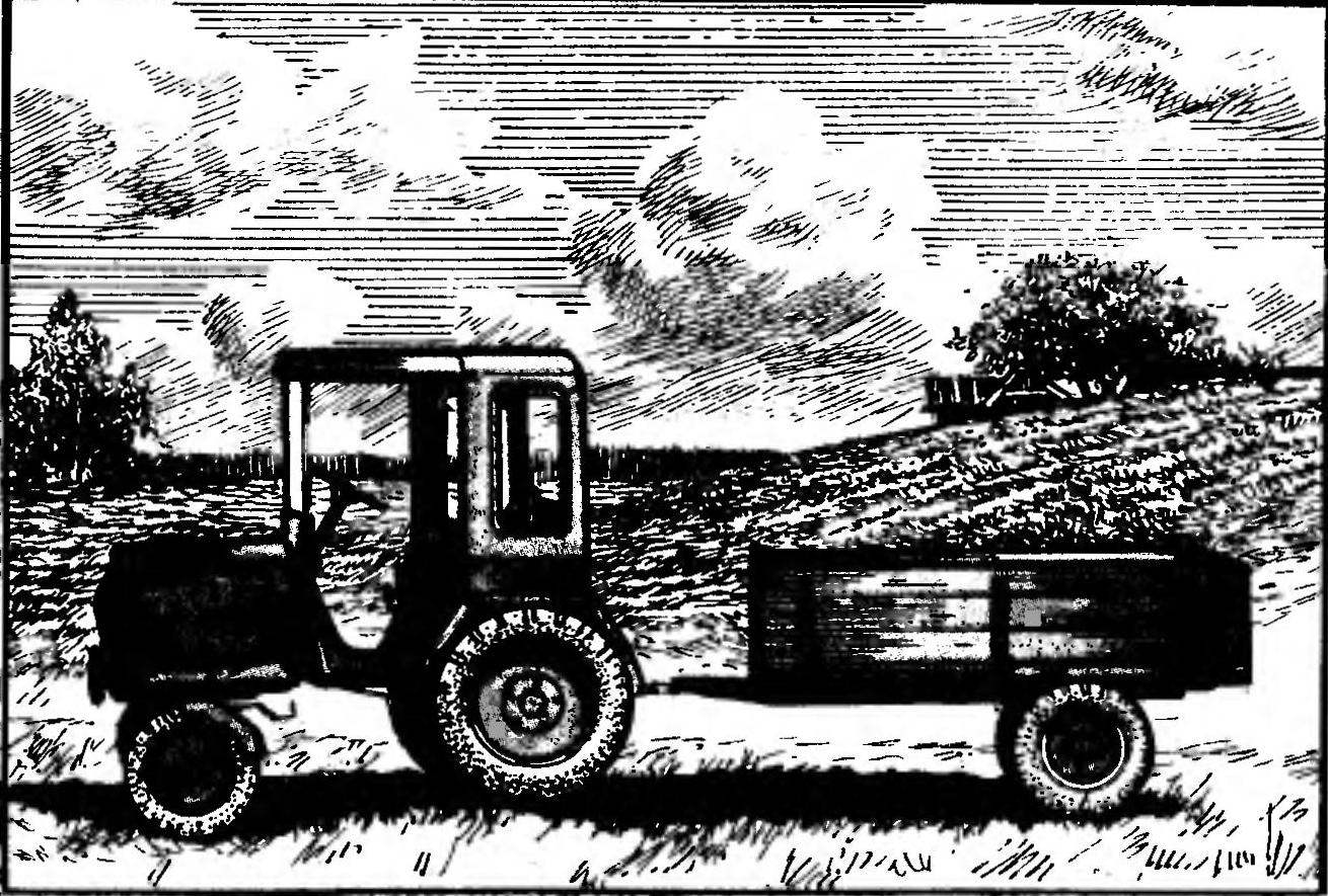
In particular, the MT, shown in the illustration, the distance from the wheel center to the edge of the plate is equal to 132,5 mm. After doubling received 265 mm. And the track width of the tractor 765. Then: 765 mm — 265 Mm = 500 mm. It is this length must be elements of the rear axle connecting the two plates with each other. And as the material is best suitable area of appropriate sizes. For example, the rear elements, which would bear essentially the entire load will approach the area 70S 70 mm, while for the front you can restrict the area 35 X35 mm.
 
Well and how to weld them to the plates without breaking the alignment of the gears!
 
Wheel at this stage it is advisable to disconnect. But the primary shafts of the gearboxes are temporarily bonded to each other using the segment of support pipe. And its internal diameter must be such that the primary shaft gear units would be in it tight enough. Inserting in its place the connecting elements of the area length (for this version of MT) 500 mm, welded to the ends of the latter to the plates, after which the auxiliary tube is cut and removed.
 
Frame min and t R a C t o R a (see Fig.) also welded. It can be made out of pipe segments, channel or area of appropriate size, and the required reserves of strength. In the present embodiment, the side members of the frame of MT — segments of a seamless steel pipe GOST 8734-75 external diameter 60 mm n a wall thickness of 5 mm. the Length is determined based on the planned dimensions of the mini-tractor, with the driver’s seat and size of the power unit, n is 1190 mm. the side members are welded to the front upper end plate of the gearbox. The connection is enhanced by the gusset in a horizontal n vertical planes, keeping parallel to the main power elements. With regard to the shape of the power unit and other major nodes of MT welded frame-arc power unit. In the present embodiment, material for its production was also
 
seamless steel pipe, but with an outer diameter of 27 mm n wall thickness of 3.5 mm.
 
Attaching rear wheels to the gears, install the front side frame MT on stands (temporary) so that the spar is parallel to the surface of the earth. Then determine the height of the bushings of the slewing mechanism of the front, steered wheels. Welded to the side members of the channel 100X X 60 mm (seam solid, bottom) and the crossmember (area 30X30 mm, top). In the sides (strictly in the middle! channel, enhanced fatty pads, that a hole is drilled under the swing axis with a diameter of 30 mm.
 
Front axle (see picture). homemade. Details of the slewing mechanism are machined after you have determined the height of the bushings. Then build the left and right nodes of the slewing mechanism to the front wheels. From the pipe a suitable cross section cut out two segments of appropriate length (calculated based on track width and other parameters associated with the nodes of the slewing gear Assembly with wheel). Being welded to the right (left) sleeve of the slewing nodes — on the one hand, and on the other to the hub node of the swing of the front axle, they will serve as the beams swing.
 
Assembled the front axle down under the frame of MT. When combining holes (in the hub site swing and the sidewalls of channel frame) is inserted into the axis of the swing — bolt MLO, tighten the nut n raskryvayut. Chassis ready.
 
The location of units and parts on the chassis, it is possible to tell, typical. The rear axle housing is the gearbox main gear. A flexible coupling connecting the shaft of the main peredachi with the primary shafts final drives from the sidecar of SZA. If you get such fails they can be replaced with homemade. As an elastic connecting element well will serve the disks with a minimum thickness of 20 mm with four holes each. Disks are inserted between the coupling halves and attach to them boltan. Here, on the rear axle, set the seat, made of a conventional chair with metal legs.
 
However, the legs had to be shortened in order to comply with the requirements of ergonomics and technical aesthetics and modern design.
 
Front panel with Polikom — old scooter “Tula 200”. Equally unusual use of the MT is found for the back of the hood of a battered motor scooter “Vyatka — Electron”. From her and another structural node: Polycom cut crosswise on the frame of the power unit and mounted on the frame of the mini-tractor.
 
Frame welded together. Moreover, the rear portion of the power unit through the area attached to the frame of the mini-tractor.
 
Wheel axle with the brake drum removed. Outside strictly according to the center for her welded steel round bars — future new shaft is of such length that sprocket on the gearbox main gear would be placed on one line, and at the end of the shaft that would make the rolling bearing. The shaft blank is inserted into the lathe for finishing to the required diameter.
 
As for the parameters of most of the chain transmission, it all depends on your existing particular saadeldin possibilities. If the main transmission is used the sprocket from the motor scooter “Vyatka — Electron”, shaft (new!) excellent work the sprocket from a motorcycle “Minsk”. Well, if the main transmission to apply Izhevsk, the asterisk “lengthened” the shaft will have to do yourself. The number of teeth is selected according to the desired gear ratio.
 
“Lengthened” the shaft is mounted on the seat Assembly with the brake drum pressed the sprocket and bearing.
 
Rulemaklng from the GAZ — 51, cropped. She is a steering shaft is inserted in the hole of the front panel so that the reducer pad was placed between the body of the target power unit and the frame. And the site columns to the cross beam (channel 100X60 mm) welded, while the steering shaft to the frame of the power unit is mounted that neither is an ordinary clamp.
 
From the site column to the corner of the mounting panel is mounted another area, which supports the end bearing of the shaft of the power unit. The angle is welded, in this, holes are drilled for fastening the bearing housing (see figure).
 
Other structural features of the MT should be noted that the rods used here the shift rod from the car BelAZ. The wings of the rear wheels is cut from the body of the old “cargo” of the car and attached to struts (area 25 X X25 mm). For the PTO shaft on the lower branch of the circuit provides for the installation of angle gearbox (outboard motor or from any farm). But it can not be put: it all depends on performed using the mini-tractor work.
 
Truck (trailer) with carrying capacity 0,5 t — homemade (see figure). Its frame is made of tubes, racks of wheels and the outer wheels from the truck for transportation of the boat “Progress”. You can, of course, to simplify the design, and taking the entire wheel and strut Assembly — boat “Progress”. The body of the trailer made of wood. Side and rear sides open.
The hitch mechanism of aggregates even in
 
respects similar to those used on standard commercially available tractors, but instead of the power cylinder is driven by a conventional lever having the latch. On top of that made the mechanism detachable. Assembled on a metal baseplate (STZ 5 mm thick) with a hole for passage of the PTO shaft”
Welded to the plate 2 area. In the upper part to the corners of the welded sleeve for the shaft (axis) of the lifting levers. At the bottom of the drilled holes for the axes of the longitudinal rods.
 
Traction is made from a strip of steel St3 (thickness 5 mm, width 50 mm). As balls for ball joints used similar items from ball bearings of the appropriate size. To drill holes in them, the balls are let go in the charcoal (lay in a burning oven and leave there until cool). Technological repeating this operation twice, start drilling, not giving the ball to heat up.
 
Drill the diameter of the balls, but not completely, leaving on the exit hole of smaller diameter. Of course, this work is not to hurry, but the hinges but work with such balls excellent.
 
The entire hitch mechanism of the tractor is mounted with four bolts.
 
Plow many homebrew, is based on the Coulter. At the same old stand at the top of the bend cut off and cut and welded “area of attachment”. Case increase, privaris to the blade top and the rear end of the steel strip (preferably steel jointers Л65) width of 50-70 mm and a thickness of 5 mm. Suture treated flush. And in the bottom of the rack is welded triangle and the emphasis for field Board.
 
The entire circuit adjustment and control the plow from the tractor. Plough frame from the metal strip (St3) with a thickness of 10 mm and a width of 60 mm.
 
Hilling potatoes, the author recommends to perform a regular horse trailer Hiller. It is not difficult to do, of course, and mounted the Hiller, but the use of such planting potatoes should be performed with strict observance of the distances between the rows. Even the rows to be perfectly smooth, though almost everywhere we have the tubers are dug into the soil immediately behind the plow, when the above requirement is not practicable.
 
To increase the adhesion of the rear wheels with the ground provided by the use of special cleats, and hanging additional weight to the frame of the mini-tractor.
 
The author constructs deliberately moved away from specifying the sizes of various components and parts. Most importantly, in his opinion, the idea at the basis of any other technical solution. By understanding this idea, a true homebrew will find a way of its realization, focusing on their own “material database”, on their specific capabilities. And for beginners, it might be useful and more detailed elaboration of the design in sketches and drawings.
 
V. BOLDYSHEV, Vologda region

Recommend to read

  • HANGER-CLIPHANGER-CLIP
    To embed in the wardrobe small, but long toilet articles — scarves, belts, ties — usually on the doors do metal braces. However, they are very inconvenient to use: hang items in several...
  • THE CARRIER ROCKET “VOSTOK”THE CARRIER ROCKET “VOSTOK”
    "I looked at the ship, which was in a few minutes to go in the unprecedented flight. He was handsome... I Thought that this beauty is eternal and will remain for the people of all...