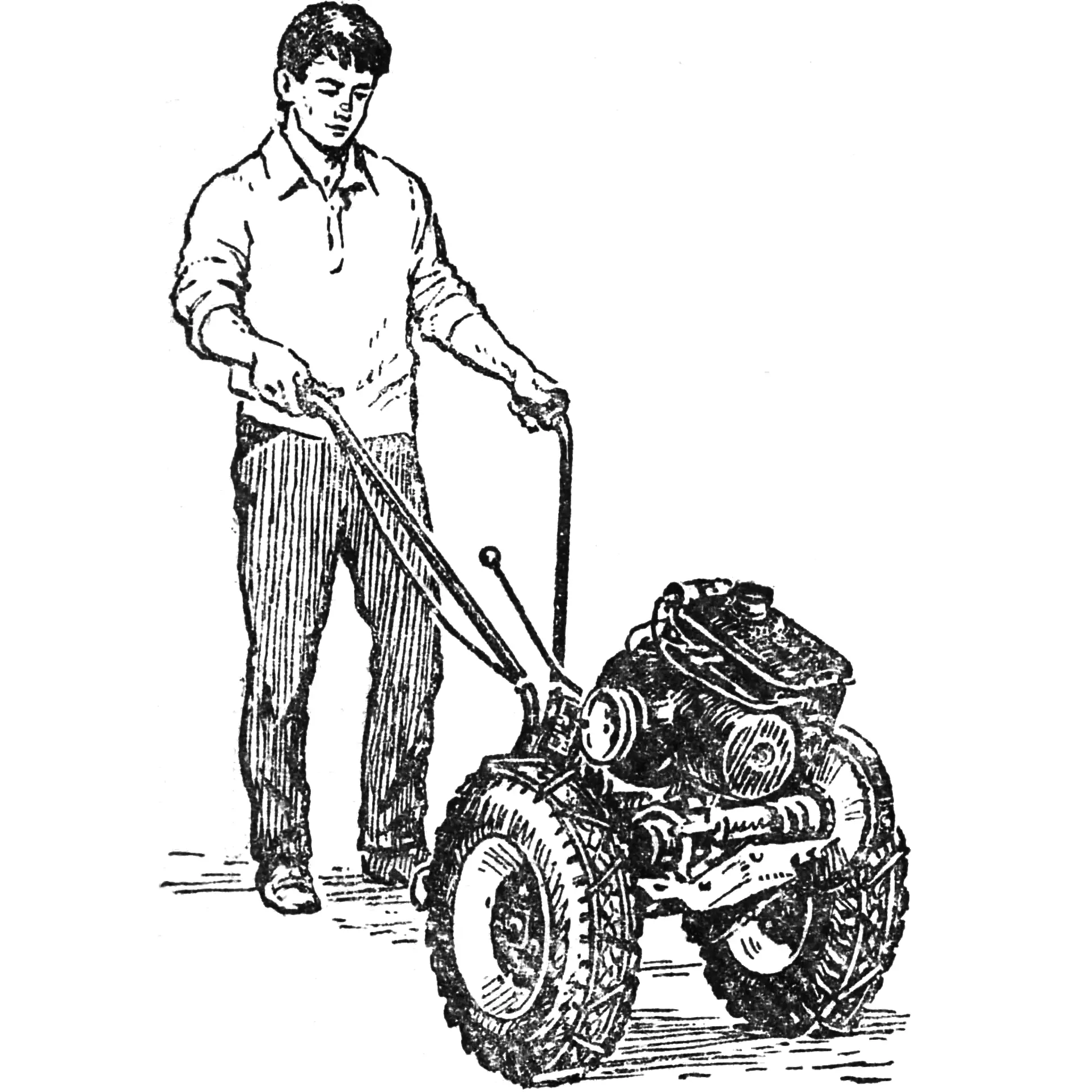
Which exhibition exhibit is the most interesting? Obviously, the one with the most visitors, the one most often aimed at by camera lenses.
That exhibit at the 1984 Moscow City Exhibition of Youth Scientific and Technical Creativity was the “Vyatka-1M” walk-behind tractor, built in the auto-design club of the Palace of Pioneers and Schoolchildren named after N. K. Krupskaya in Moscow’s Baumansky district.
Club members, brothers Alexander and Vladimir Samsonov — now students at the Moscow Automobile and Road Technical College — took as a basis the design by engineer S. Ilyichev (see “Vyatich” from the Moscow Region, “M-K” No. 7, 1981).
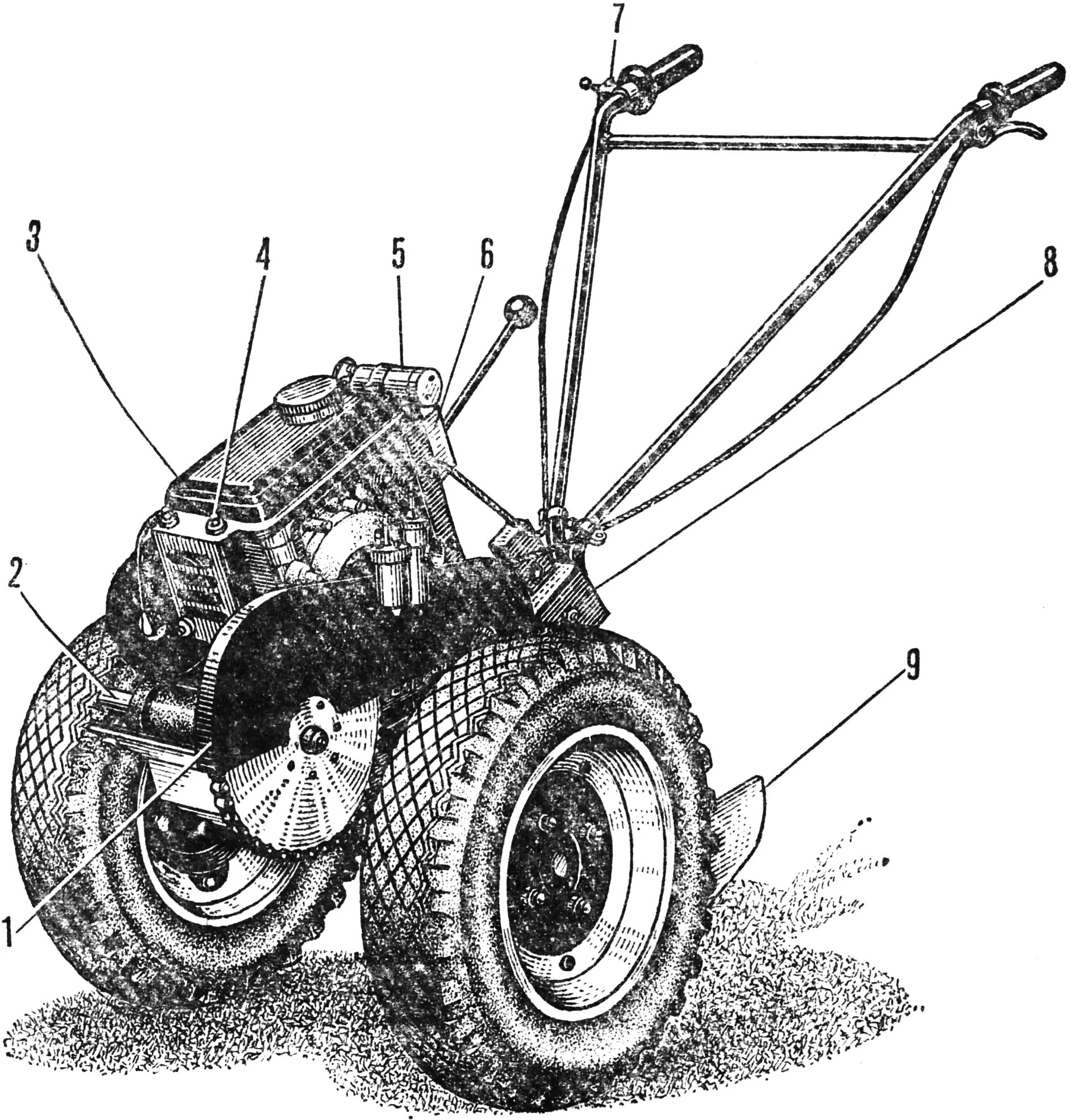
1 — protective cover, 2 — power take-off shaft, 3 — flat fuel tank, 4 — tank mounting, 5 — ignition coil, 6 — electronic ignition unit, 7 — throttle twist grip, 8 — implement shank, 9 — cultivator share.
The original design, however, did not fully satisfy the young builders. Many assemblies and parts were redesigned by them during manufacture and fine-tuning. As a result, the “Vyatka-1 M” resembles the prototype only in layout. It became more stable, more elegant, and much more convenient.
Their mentor, club leader Konstantin Ivanovich Kruglikov, talks about this work by the Samsonov brothers.
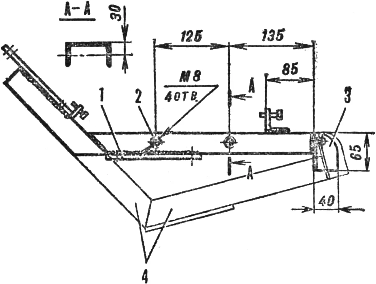
1 — drive axle platform, 2 — hole for the bracket locking stud, 3 — implement holder suspension lugs, 4 — frame section to be removed.
At first the boys fully repeated S. Ilyichev’s design. But during tests on a garden plot, shortcomings appeared. The walk-behind tractor proved unstable on turns, and it was hard to keep it in the furrow because of the high center of gravity.
It also turned out that kick-starter starting was not entirely convenient, and the engine ran unreliably — apparently the long bent carburetor pipe impaired fuel supply. Straight lugs quickly clogged with soil, and the plow threw the soil slice right onto the wheel.
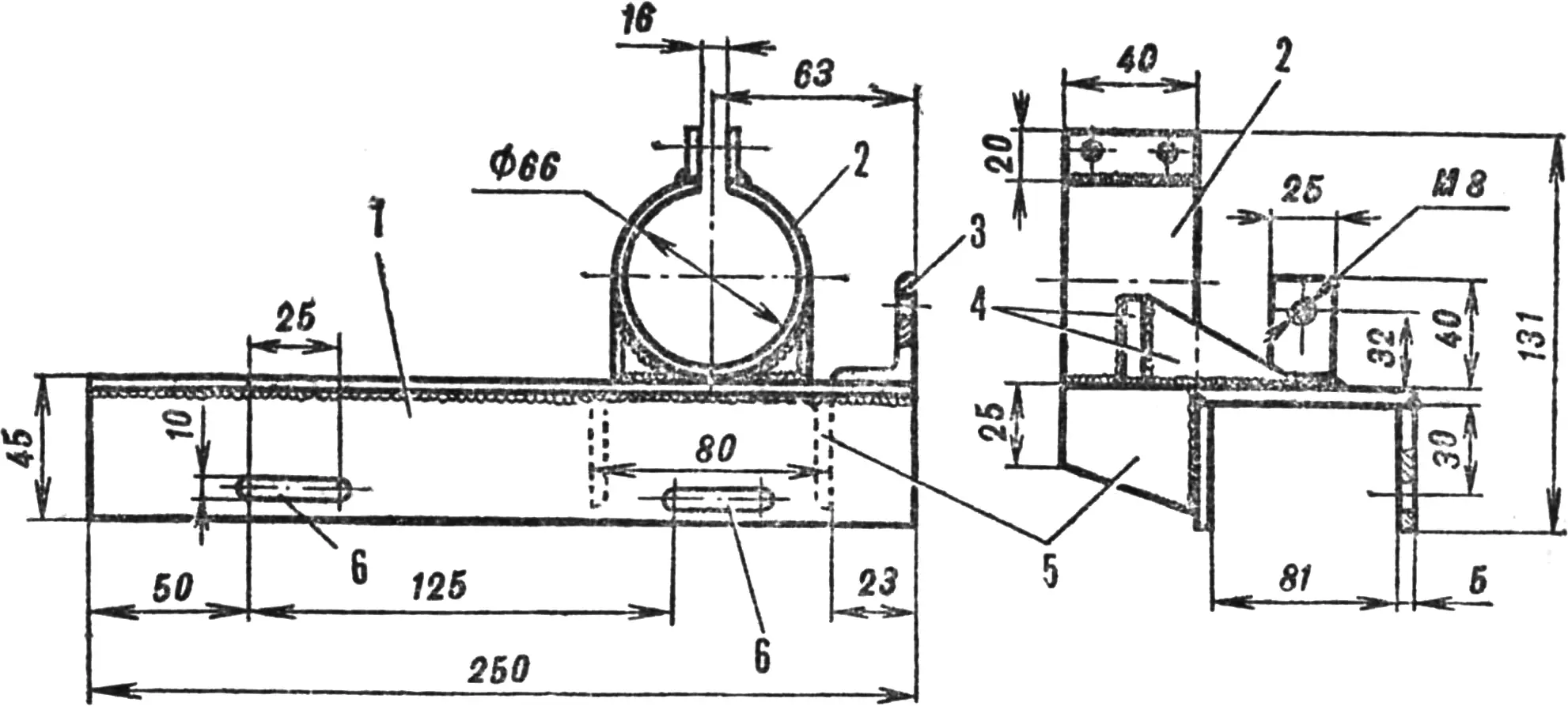
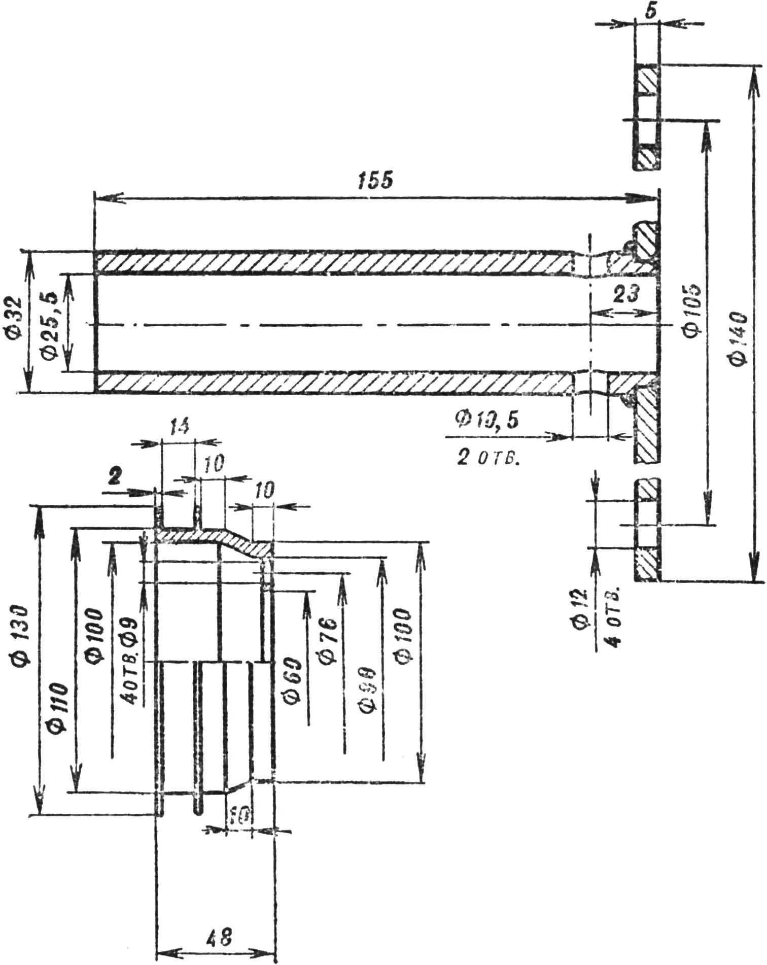
1 — base, 2 — clamp, 3 — stop angle, 4 — stiffening ribs, 5 — support, 6 — slots for locking studs.
Of course, none of this suited us, and we began thinking how to improve the machine. We decided to reduce the walk-behind tractor’s vertical overall size and, at the same time, its weight.
We started with the frame (see “M-K” No. 7, 1981, pp. 8—10). Part of the inclined beam and the entire lower beam were cut off; the drive axle platform was moved to the upper beam; the holder suspension lugs were aligned.
Then we simplified the engine mounting bracket, leaving, in our view, only what was essential: the base, clamp, support, stiffening ribs, and stop angle. We also changed how the bracket is fixed on the frame: instead of two bolts on top — four studs on the sides.
From experience we knew that a cylindrical fuel tank is not always advantageous. In this case a rectangular tank of small thickness was more suitable. We attached it to the cylinder-head cover and the engine-bracket clamp.
As a result, the walk-behind tractor’s “height” decreased by 350 mm. Lowering the center of gravity combined with an increased wheel track of 500—700 mm (depending on disc turn) gave the design the needed stability.
The long bent carburetor pipe also raised doubts — a short, stock pipe is better. So we returned to it. To make the engine run more reliably, we used an electronic unit and an ignition coil, and instead of a kick-starter we fitted a starting pulley on the fan shaft.
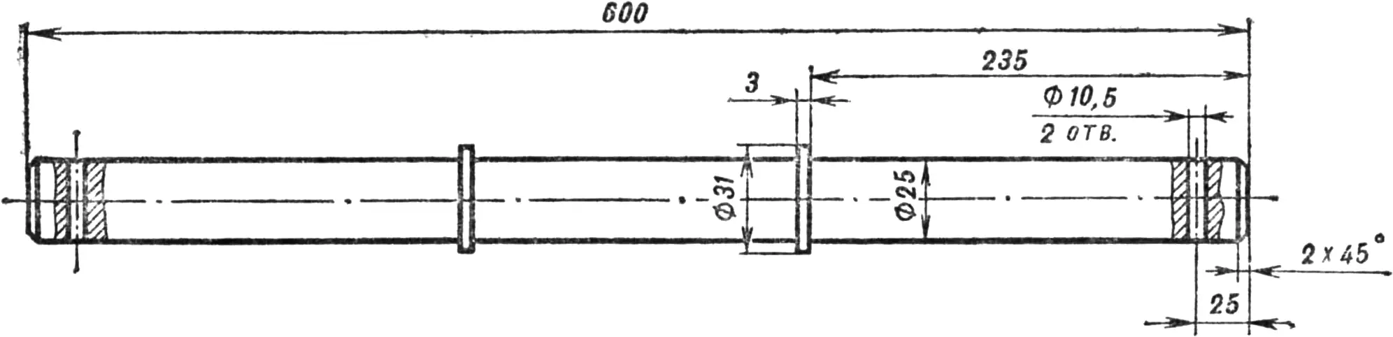
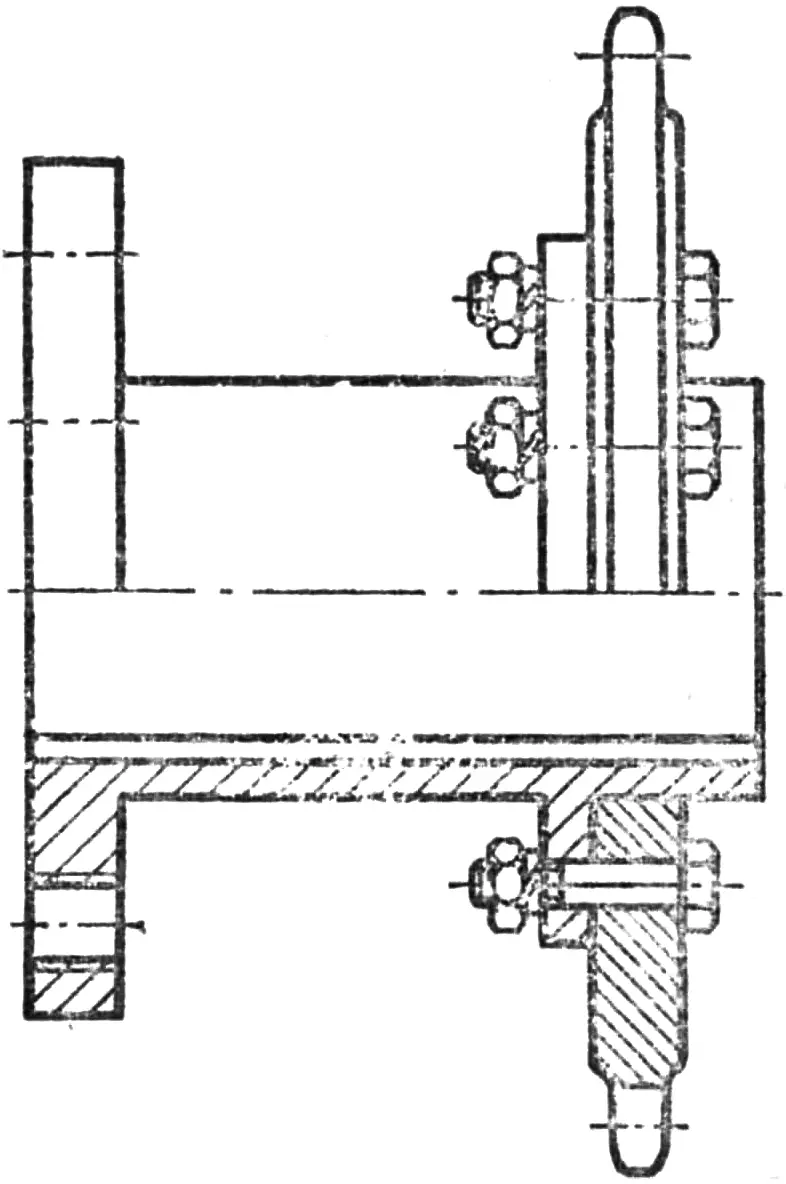
It was decided not to change the transmission layout. However, the intermediate and drive axles were made by us. For simplicity we used a keyed connection of the sprockets to the shafts rather than a splined one. And one more thing. To make it easy to select optimal gear ratios, the sprockets were made separately from the hubs and bolted together.
For safety, the upper chain is enclosed by a cover.
Our implement holder with control handles looks somewhat different: the handles can be locked in any of three provided positions.
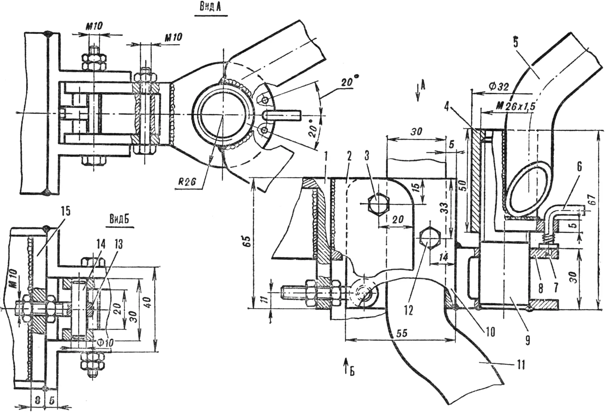
1 — frame, 2 — holder suspension lugs, 3 — holder suspension bolt, 4 — bushing, 5 — control handle, 6 — lock link, 7 — lock, 8 — lock plate, 9 — pin, 10 — implement holder, 11 — bent implement shank, 12 — implement suspension bolt, 13 — adjusting bolt, 14 — adjusting-bolt axis, 15 — end wall.
As a plow we use a cultivator share with a shank bent rearward so that soil does not bury the right wheel.
We also took a critical view of the throttle lever, believing it unsuitable for controlling a walk-behind tractor’s engine: a twist grip is better.
Now about the wheels. We decided not to use a support wheel and preferred two wheels from an S3A motorized sidecar. The lugs on them were set at 45°, in a herringbone pattern, so they would self-clean during plowing. Instead of chains we fitted rims made of steel strips…
The boys named their walk-behind tractor “Vyatka-1M”. The effort they put into improving the “Vyatich” design was not wasted — the machine runs reliably. For a second season already they have been plowing heavy loam with it. And fairly quickly — three hundred square meters in one hour to a depth of 220 mm.
The walk-behind tractor’s intermediate shaft also serves as a power take-off shaft. By connecting it to a pump, circular saw, or mower, a whole range of additional farm jobs can be done.
Recommend to read
 RELIABLE HEAD PROTECTION
The human neck is very perfect mechanism that performs many vital functions. However, it is very compact, flexible and surprisingly agile. All this allows to consider it one of the most... With a trailer on a Niva
The favorite car in the countryside is, without doubt, the full-wheel-drive, high-clearance VAZ 2121 “Niva”. Unfortunately, our industry does not produce trailers specifically for this...
