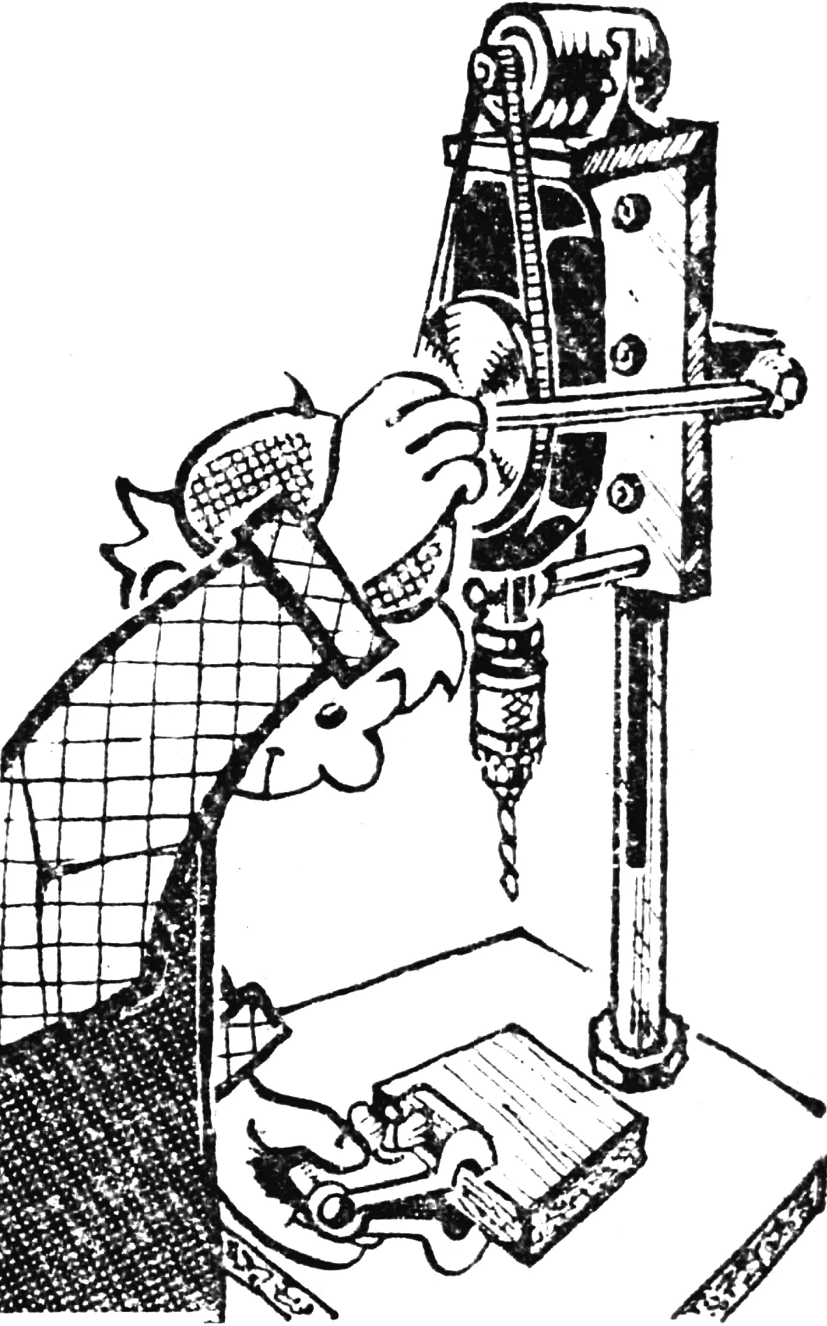
I offer hobbyists a homemade desktop drilling machine that uses a hand drill.
A hollow tubular column is mounted on a sturdy base, and a rod is installed inside it so that it can move. On one side of the rod a toothed rack is cut for the vertical feed drive, and on the other side a flat is machined for attaching a bracket with a guide strip through a longitudinal slot in the column. A hand drill and an electric motor are mounted on the bracket. The drill is driven from the motor by a V-belt drive. Vertical feed of the assembly is provided by a mechanism housed in a separate casing. The overall dimensions of the machine depend on the chosen column length and base size; for the sizes given, the vertical feed travel is 100 mm.
More details about the machine parts.
The base is a steel plate measuring 320X320X8 mm. A Ø 35 mm hole is drilled in it for the column, and four threaded holes at the corners are made for the legs.
A thick-walled steel tube with an outer diameter of 35 mm and an inner diameter of 23 mm is used as the column. An M35 thread is cut on one end for fastening to the base. On the other end, a longitudinal slot 14 mm wide is milled (for the bracket’s guide strip) and a rectangular window is cut for mounting the pinion of the vertical feed drive. Four radial M5 holes are intended for fastening the vertical feed mechanism housing to the column.
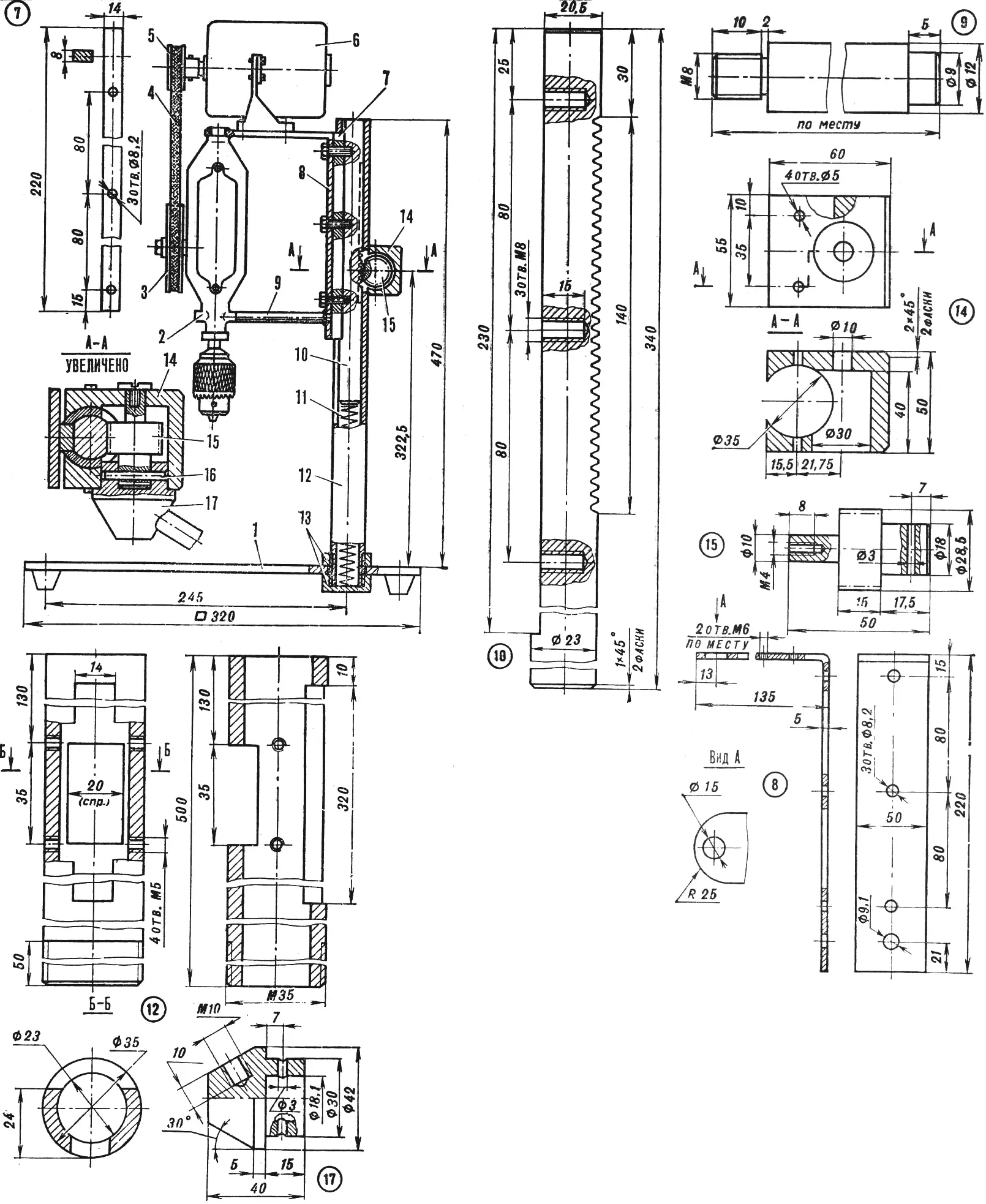
1 — base, 2 — hand drill, 3 — driven pulley, 4 — belt, 5 — driving pulley, 6 — electric motor, 7 — guide strip, 8 — bracket, 9 — lower stop, 10 — rod, 11 — spring, 12 — column, 13 — column nuts, 14 — vertical feed mechanism housing, 15 — pinion shaft, 16 — pin, 17 — handle hub.
The L-shaped bracket is bent from a steel plate measuring 355Х 50X5 mm. Its horizontal flange has two M6 holes for the motor bracket and a Ø 15 mm hole for the shortened drill handle. In the vertical flange, a Ø 9.1 mm hole is drilled for the drill’s lower stop and three Ø 8.2 mm holes for attaching it to the rod through the guide strip.
The drill is mounted on the bracket as follows. The drill handle is cut off 5—10 mm from the base. A stop rod is screwed into the side handle socket. After the drill with the lower stop is set into the Ø 15 mm and Ø 9.1 mm holes of the bracket, it is welded in place, carefully checking that the longitudinal axis is parallel to the vertical axis of the bracket flange.
The vertical feed rod is a steel bar Ø 23 mm, 340 mm long. Its toothed rack with m = 1.5 is cut over a length of 140 mm, and the flat milled on the opposite side is wide enough for attaching the bracket’s guide strip.
The feed mechanism housing is fastened to the column with four M5 screws. A pinion shaft of the feed mechanism, meshing with the rod’s toothed rack, is installed in its bored seat Ø 30 mm. The handle hub is connected to the shaft with a pin.
For convenient operation, the rod in the column is spring-loaded. The blind fastening nut of the column serves as the lower stop for the spring.
The design uses an electric motor of the DO-50M type. Its power is 50 W at a rated speed of 1420 rpm. If a motor of another make is installed, the required tool speed is obtained by selecting the pulley diameters of the V-belt drive or by fitting stepped pulleys.
“M-K” 7’86, D. KHANMIRZOEV, Shemakha, Azerbaijan
Recommend to read
 “SOFT” CLUTCH
To connect the motor shaft with the driven shaft in the mechanism is never easy. For example, electromotor and water pump also require accommodation on a single rigid frame, which would... LOW-VOLTAGE POWER FROM THE NETWORK
Compact consumer electronic devices gadgets such as watches, alarm clocks, radios, toys, weather stations and other similar devices are available in almost every home. Regularly and...
