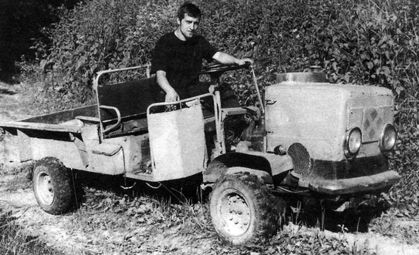
Viktor Dmitrievich Berezhnoy is a native of Valday. By his main profession, he is a highly qualified welder. However, in the district center it’s difficult to find well-paid work. He had to be both a tailor and a reaper. The only constant was Berezhnoy’s passion for technical creativity. It was this that helped him out in difficult times.
Take, for example, the multi-purpose tractor “Little Brother”, built by Berezhnoy several years ago. “Little” because there is also a “Big Brother” — a wheeled all-terrain vehicle, for which Viktor Dmitrievich received a prize from the television program “Be Your Own Director” in 2002.
So, the tractor was needed by our amateur designer for urgent matters at the dacha. It was necessary to deliver building materials, fuel and fertilizers to the site, to transport the harvest to the city… In the yard there was only one “horseless” motor-block trailer. True, in the shed there was a supply of materials necessary for any craftsman: steel profiles of various sections, sheet metal, pipes, wire, fasteners. As well as tools and welding equipment. The least remained — to design and build a tractor for the trailer. And soon it was built.
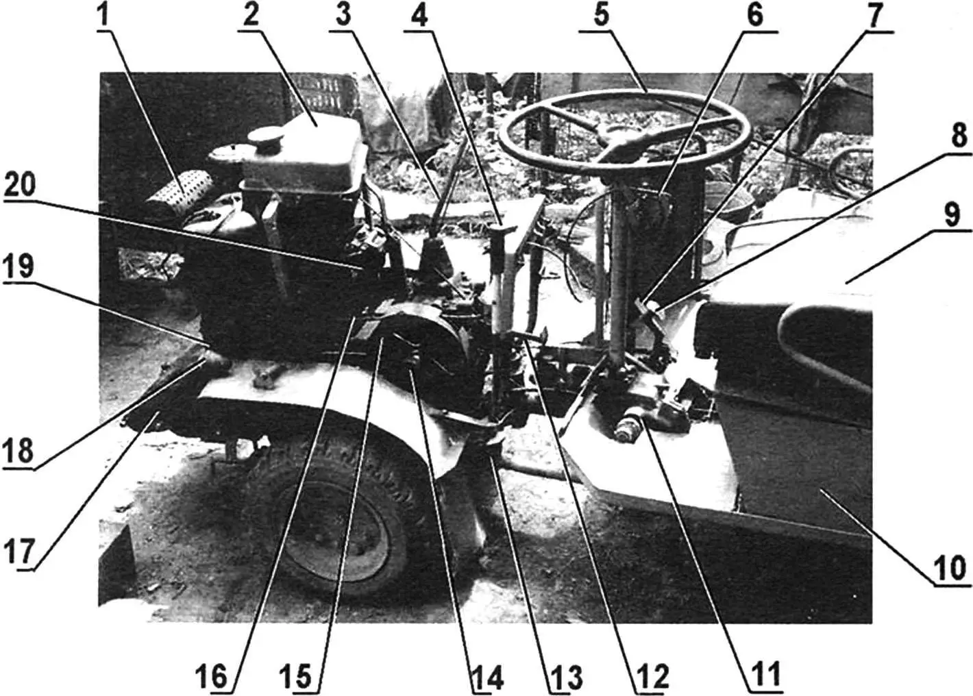
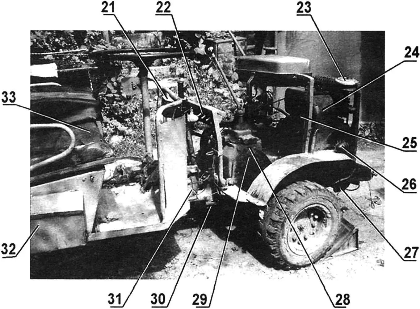
1 — muffler housing; 2 — fuel tank with capacity of 15 l; 3 — gearbox lever; 4 — winch lever; 5 — steering wheel with column (from GAZ-51); 6 — clutch handle; 7 — throttle pedal; 8 — trailer brake pedal; 9 — driver’s seat; 10 — trailer body; 11 — steering mechanism (from GAZ-51); 12 — tractor brake pedal; 13 — steering joint; 14 — additional support for primary gearbox shaft; 15 — double-groove pulley on primary gearbox shaft; 16 — tension pulley (clutch); 17 — tractor frame; 18,26 — side lights; 19 — double-groove pulley on engine output shaft; 20 — fuel filters for coarse and fine cleaning (from GAZ-51); 21,22 — panels for low and high beam toggles, turn indicators; 23 — air filter housing; 24 — UD2-M1 engine; 25 — kickstarter; 27 — mini-winch; 28 — gearbox (from GAZ-51); 29 — gearbox output shaft; 30 — articulation pin of tractor and trailer; 31 — turning unit; 32 — tool box; 33 — passenger seat
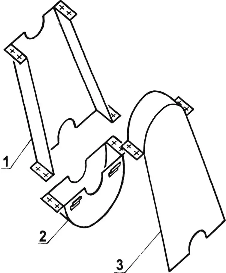
The designer’s hand also touched the trailer: the drawbar is equipped with a homemade coupling unit; the body is extended in length by 220 mm and reinforced at the front with a steel angle, the fenders are raised to allow the use of larger diameter wheels; the passenger seat is fenced, and the driver’s seat is equipped with a steering mechanism with a shortened column from a GAZ-51 car.
For fairness, one should immediately note one feature or, rather, a drawback of the tractor control system: when turning, say, to the right, its steering wheel must be turned… in the opposite direction, that is, to the left. And vice versa. This paradoxical result was caused by the designer’s attempt to maximize the simplification of the steering drive kinematics. In this case, the steering mechanism pitman arm (from a GAZ-51 car) is directly connected with a single rod to the left corner of the tractor frame. Of course, an intermediate rocker, another rod, and moving the ball joint to the right corner of the frame should have been introduced immediately. But father and son Berezhnoy (and only they drive the “Little Brother”) quickly adapted to this feature of his.
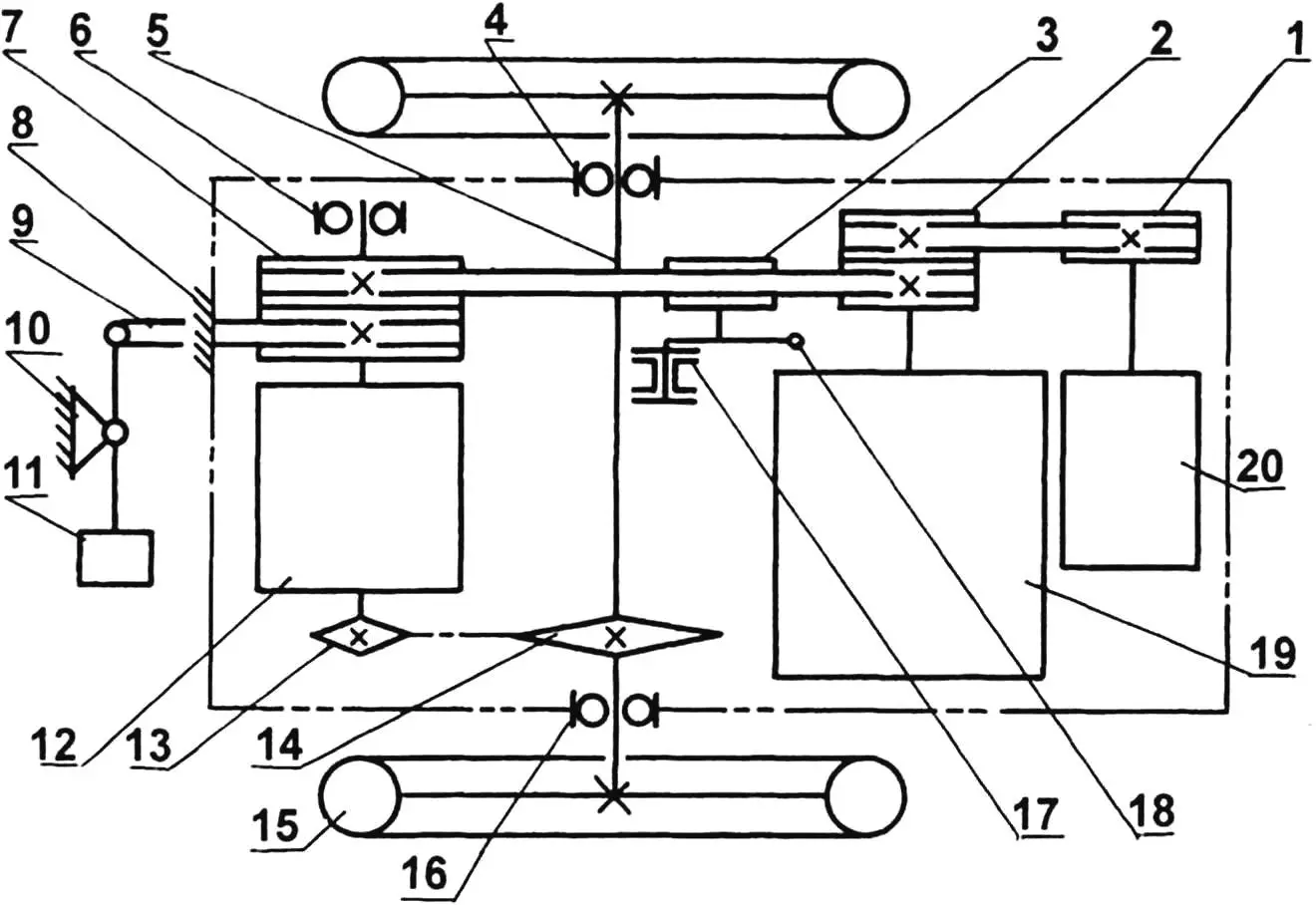
1 — generator drive pulley; 2 — double-groove pulley on engine output shaft; 3 — tension pulley (clutch); 4,16 — bearings 208 of drive axle; 5 — drive axle shaft; 6 — bearing 205 of additional support for primary gearbox shaft; 7 — double-groove pulley on primary gearbox shaft (left groove of pulley — drive, right — brake); 8 — fixing of upper end of brake V-belt; 9 — tension end of brake V-belt; 10 — hinge support of brake pedal; 11 — brake pedal; 12 — gearbox (from GAZ-51 car); 13 — drive sprocket (z = 12, t = 19.05); 14 — running sprocket (z = 34, t = 19.05); 15 — wheel (from electric car, 2 pcs.); 17 — hinge support of tension pulley; 18 — tension pulley drive; 19 — UD2-M1 engine; 20 — generator.
All V-belts have type A cross-section
In the new spring, Viktor Dmitrievich decided to use the “Little Brother” in garden work, as they say, to the full. He equipped the tractor with hydraulics, for which he removed the body and placed on the trailer’s wheel axle a power cylinder, pump and tank with hydraulic fluid (from a PAZ bus), and under the steering wheel — a distributor (from a DT-20 tractor). The mounted plow was attached directly to the power cylinder.
However, on the limited area of the dacha garden, it was difficult for the “Little Brother” to turn around. Then the designer developed a special mini-winch with drive from the tractor engine and a simple guide mechanism attached to the front bumper, and equipped the plow with a cable and front wheel. And he began to plow the land together with his son: one of them controls the engine and winch, the second — the plow. Things immediately went faster and, most importantly, the quality of work became higher.
TRACTOR CONSTRUCTION
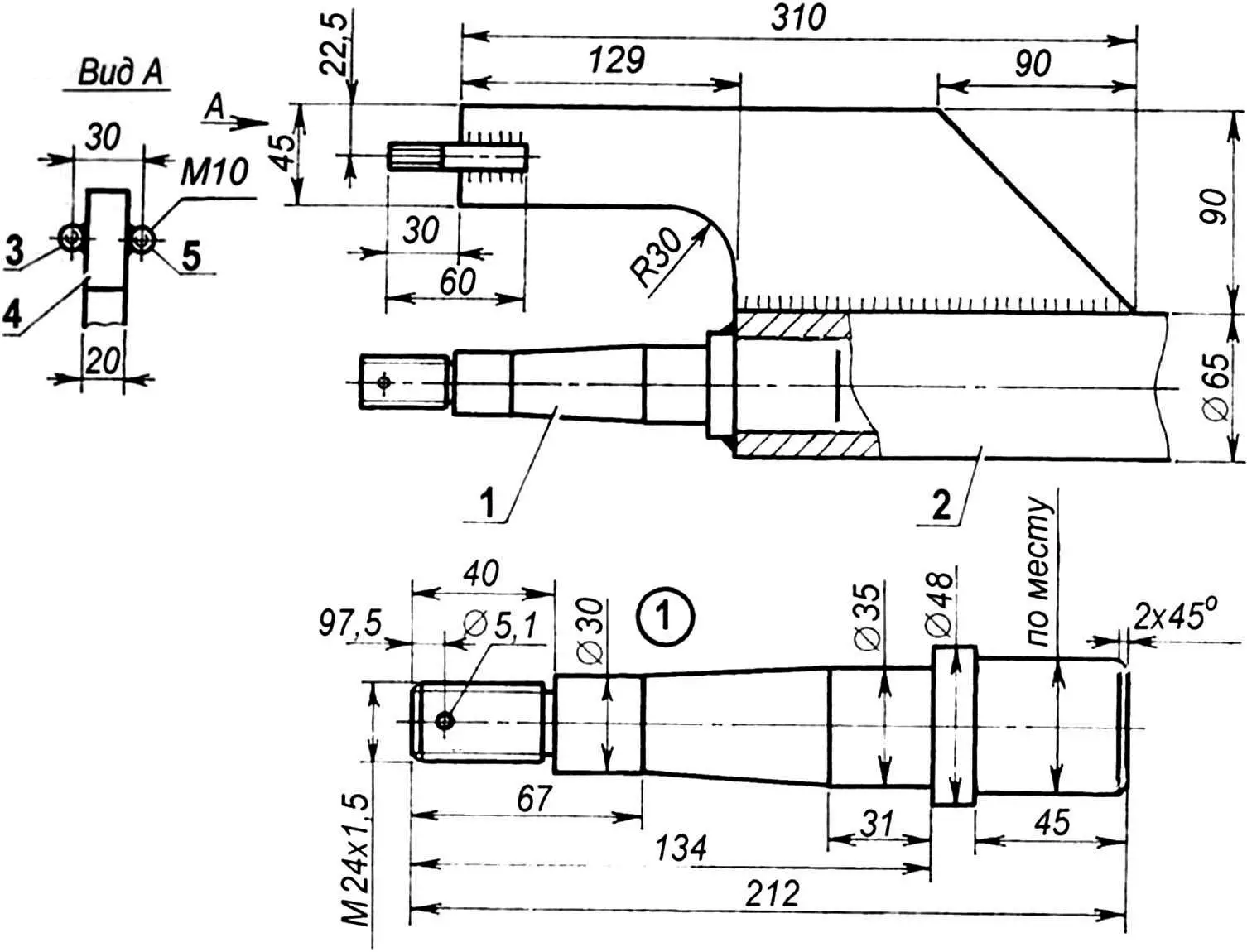
All tractor units are assembled on a rectangular frame welded from steel profiles. In front, on two angle brackets, a 2-cylinder UD2-M1 engine weighing 90 kg and power of 8 hp at 3000 rpm is secured with four bolts. Above the engine, on angle posts not shown in the figure, — a fuel tank with capacity of 15 l, air filter, muffler, block of coarse and fine cleaning filters (from GAZ-51).
Behind the engine — space for the gearbox (also from GAZ-51). For its installation, two brackets are provided: a stationary left one — a longitudinal steel plate with holes in place — and a removable right one (although a copy of the left one could be placed in its place. But this is how the author of the design made it, so we present his version).
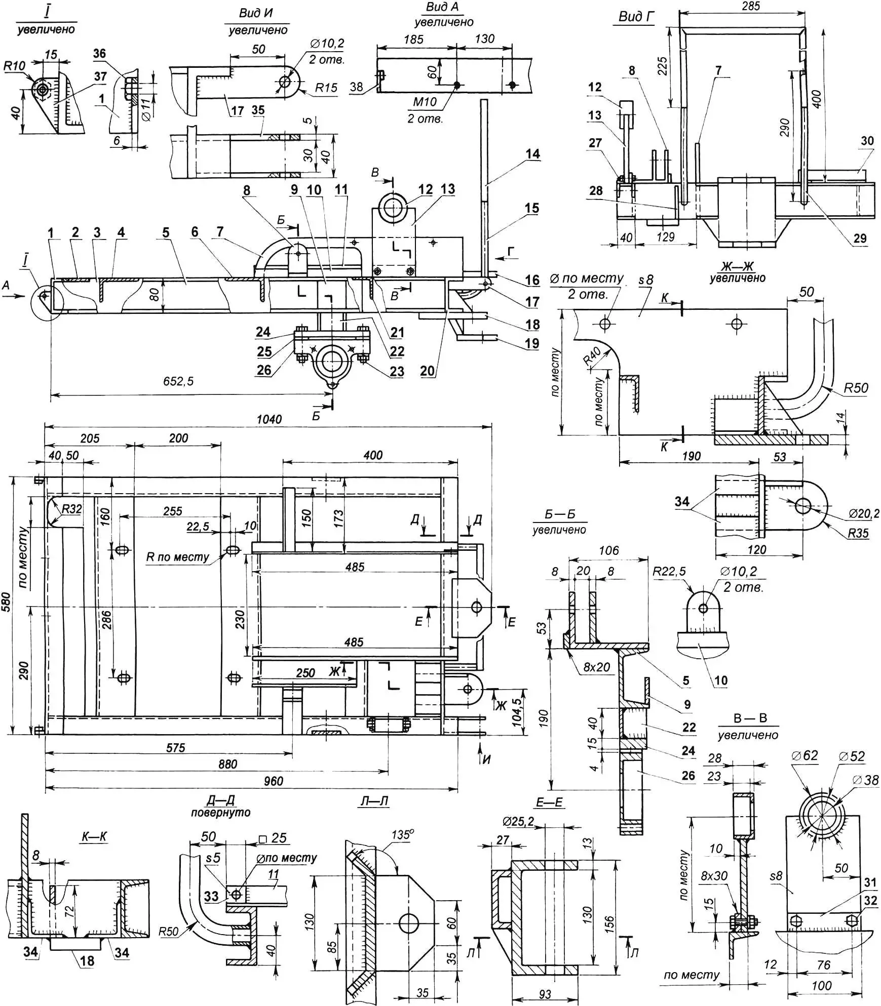
1,20 — front and rear bumpers (profile 80x40x8); 2 — generator shelf (strip 50×5); 3,5 — side members (channel No. 8); 4,6 — engine shelves (angle 90x56x6); 7 — left gearbox bracket (sheet s8); 8 — tension pulley eye (strip 45×8); 9 — reinforcing wall (strip 65×8, 2 pcs.); 10 — reinforcing bar (strip 20×8); 11 — right gearbox bracket bed (angle 28x28x3); 12 — bearing housing of additional support for primary gearbox shaft; 13 — additional support (sheet s8); 14 — control panel bracket (angle 28x28x3); 15,29 — bracket supports (tube 27.4×4); 16,19 — turning unit eyes (sheet s13); 17,35 — winch lever mounting loops (strip 30×5); 18 — steering eye (sheet s14); 21 — crosspiece (angle 50x50x5); 22 — post (channel No. 6.5, 2 pcs.); 23 — bolt M16 (4 pcs.); 24 — drive axle support (strip 36×15, L175, 2 pcs.); 25 — adjusting washer (4 pcs.); 26 — drive axle bearing housing (2 pcs.); 27,32 — bolts M10; 28 — gusset (sheet s8); 30 — drive chain housing mounting bracket (angle 28x28x3); 31 — additional support mounting bracket (strip 30×8, L100); 33 — overlay (sheet s5): 34 — steering eye mounting brackets (angle 50x50x5); 36 — nut M10 (2 pcs.); 37,38 — front mounted implement loops (sheet s6)
Under the frame — the drive axle, rotating in two bearings 208, the housings for which were selected from Berezhnoy’s available spare parts, and the covers were turned additionally.
The force from the engine to the wheels is transmitted by two drives: from the crankshaft tail to the gearbox by V-belt (with type A cross-section belt), and from the gearbox to the wheels — by chain (with pitch t = 19.05).
Why was a V-belt drive used? Because Berezhnoy on all his homemade vehicles prefers to use a tension pulley as the clutch mechanism. He believes that such a clutch is more reliable and maintainable than any other. At least, personal experience convinced him of this more than once. The tension pulley with diameter of 120 mm on the tractor is located at the end of the turning lever and is actuated by means of a cable in a sheath, the end of which is fixed on the clutch handle under the steering wheel.
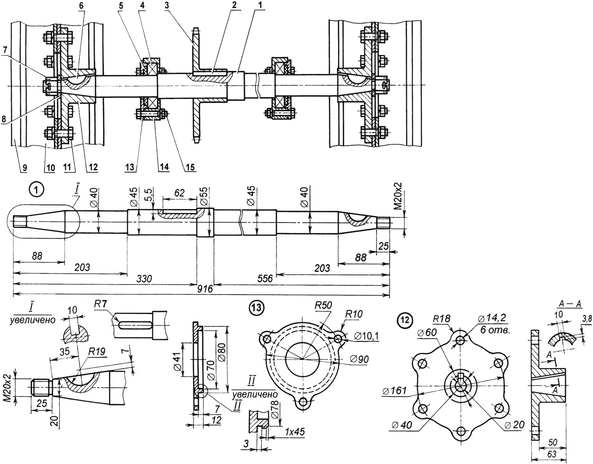
1 — running shaft; 2 — prismatic key 14x9x62; 3 — running sprocket (z = 32, t = 19.05); 4 — bearing 208 (2 pcs.); 5 — seal (2 pcs.); 6 — segment key 10×15 (2 pcs.); 7 — slotted nut M20x2 (2 pcs.); 8 — spacer washer (2 pcs.); 9 — wheel tire (from electric car, 2 pcs.); 10 — split wheel disk (2 pcs.); 11 — bolt M14 (2×6 pcs.); 12 — wheel hub (2 pcs.); 13 — bearing housing cover (2 pcs.); 14 — bearing housing (2 pcs.); 15 — bolt M10 (2×3 pcs.).
Bolts connecting disk halves are not shown
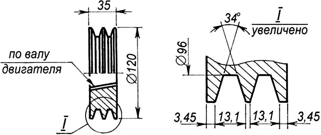
A double-groove pulley is fitted on the output tail of the crankshaft. The first groove is intended for the running belt, the second — for the generator. The generator itself is installed in front of the engine on a special shelf made of steel strip welded to the front bumper (holes in the shelf for generator mounting bolts are not shown in the frame drawing, but a cutout in the right front corner of the frame is shown — for the engine fan housing).
In addition, another V-belt is used in the tractor’s brake mechanism. As a rule, this mechanism is used at low speeds and as a supplement to the trailer’s brake system, which is considered the main one.
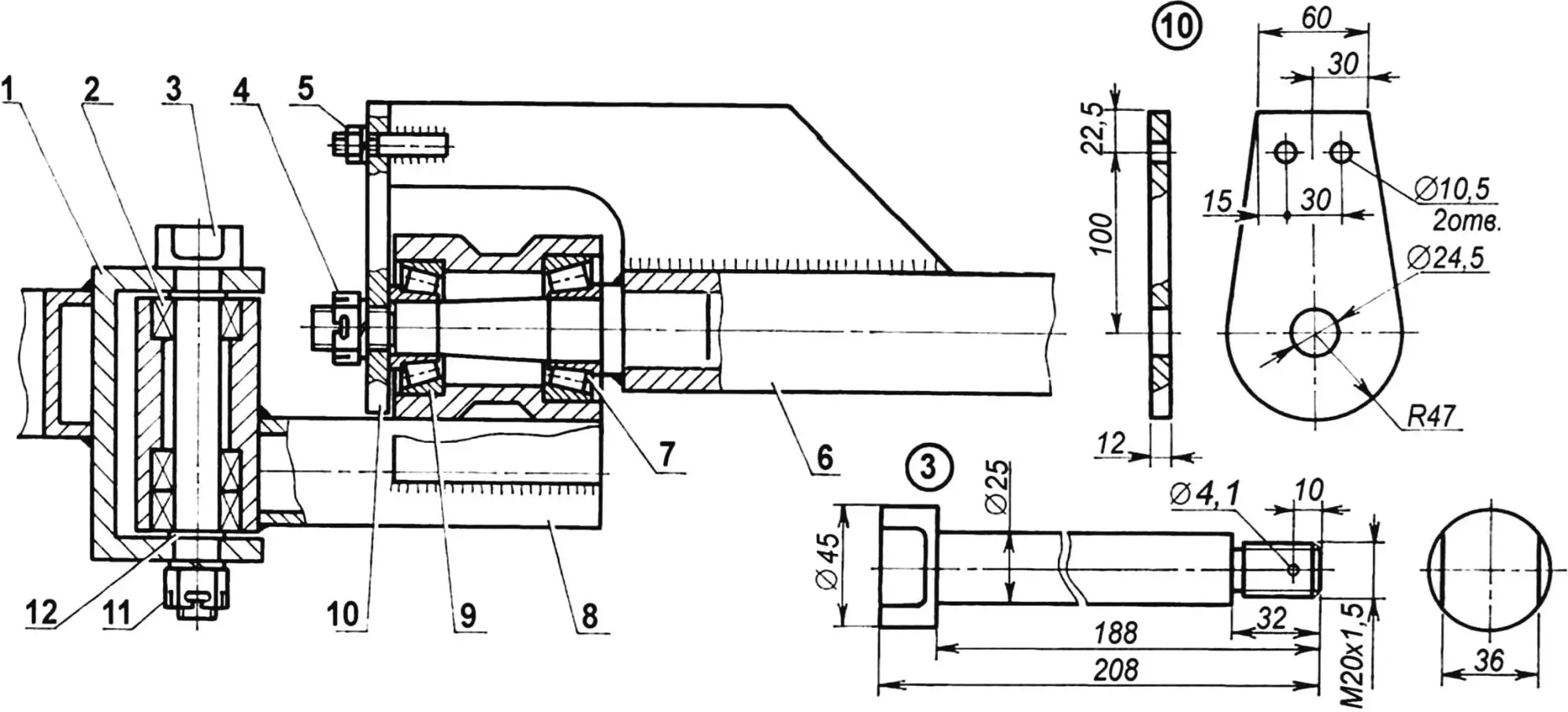
1 — tractor frame eye; 2 — roller radial needle bearing 4074105 (3 pcs.); 3 — articulation pin of tractor and trailer; 4 — nut M24x1.5; 5 — nut M10 (2 pcs.); 6 — coupling unit; 7 — roller tapered bearing 7607; 8 — intermediate hinge link; 9 — roller tapered bearing 7606Н;
10 — trunnion bracket (steel, sheet s12); 11 — nut M20x1.5; 12 — distance washer (s5, 2 pcs.)
For this, the primary gearbox shaft is extended and a double-groove pulley with diameter of 260 mm from some agricultural machine is fitted on it. To prevent the shaft from being overloaded by bending forces, its end is reinforced with an additional support with bearing 205.
A long drive belt is fitted on the left groove of this pulley, a short brake belt on the right. The latter is cut, and its upper end is fixed on the nearest support of the control panel bracket, and the lower one is connected to the pedal on the same support. It’s enough to disengage the clutch, that is, to loosen the tension of the drive belt, and press the pedal, and the brake will “grab” the pulley and significantly slow down the “Little Brother”.
1 — needle bearing cage; 2 — carrier (tube 60×8); 3,5 — overlays (steel, sheet s5); 4 — roller bearing cage
On the gearbox output shaft there is a small sprocket connected by a roller chain to a large running sprocket on the drive axle shaft. The chain is tensioned by selecting the thickness of four adjusting washers on the bolts securing the axle to the frame.
The drive shaft is non-differential, monolithic. Rotation from the running sprocket is transmitted by it immediately to both wheels. It would seem that the gain due to design simplicity should be reduced to zero due to problems with turns. However, experience showed that there are no such problems. Even when driving on asphalt — the author of the article is a witness to this — there were no difficulties with controlling the tractor. Obviously, the tractor’s track is so small (only 860 mm!), the tires (from an electric car) and the running shaft are powerful, and the soil on which the “Little Brother” moves is predominantly loose, so in turns the wheels easily cope with overloads.
1 — inner part; 2 — sump (steel, sheet s1); 3 — outer part; material — steel, sheet s1; connection — bolts M6 (8 pcs.)
By the way, the thick tires, designed for very high air pressure (an electric car is, after all, a lifting machine), allowed Berezhnoy to noticeably improve the traction qualities of the wheels. In every free minute, Viktor Dmitrievich took a sharp knife in his hands and cut depressions along the edge in the dense rubber mass. Over time, almost “bald” tires acquired a fairly noticeable tread pattern.
No difficulties are expected with wheel mounting either. Their disks are split, on six bolts, so the tire mounting operation called “dismounting” is excluded in this case. It’s not easy, though, to manually inflate the tubes to several tens of atmospheres. But Berezhnoy has had to do this only once so far.
1 — trunnion; 2 — trailer drawbar; 3, 5 — studs M10; 4 — ridge
If we talk about specific units of the tractor design, the most complex unit is, naturally, the frame. Steel profiles of the most varied sections were used for its manufacture.
At first glance, the frame looks like a jumble of these very profiles. However, each of them fell into place not by chance, but as a result of multiple checks for operability. Following his principle of reasonable sufficiency, the designer sometimes went for obvious thickening of some joint, but sharply simplifying the form of the welded connection. This gave a noticeable gain in time, in the expenditure of effort and means.
He had to tinker longer with the turning unit, in the manufacture of which it turned out to be necessary to resort to lathe work. Since the articulation of the tractor with the trailer had to meet the principle of an “articulated” frame with two degrees of freedom, Viktor Dmitrievich, to save time (spring was pressing), settled on the first option — with an intermediate hinge link with two mutually perpendicular axes of rotation. Fortunately, all necessary parts, including needle and tapered bearings, were at hand then.
However, today the designer would advise his possible followers, who agree with this version of the turning unit, to make it even simpler. And for this, instead of triple needle bearings 4074104 and a homemade articulation pin, use standard double needle bearings 46490518 and a pin from a GAZ-51 gearbox, and instead of tapered bearings 7606Н and 7607 and a homemade trunnion — standard tapered bearings and a trunnion from the front wheel hub of the same car. Of course, if they are available.
1 — steering eye on tractor frame; 2 — ball joint; 3 — steering rod
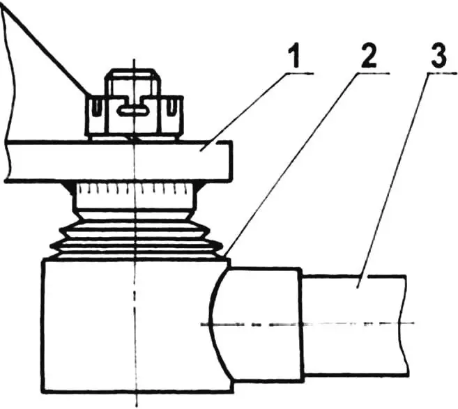
And finally. In the photo in the header, it’s clearly visible that almost all units of the “Little Brother’s” power plant are hidden by a hood, and the front bumper made of rough channel — by a more decorative chrome-plated bumper from a VAZ-2101 “kopeck” (shortened and without “fangs”).
The hood is welded from a cutout of a 1 mm thick steel sheet and equipped with metal fine-mesh screens for air access to the engine crankcase (in front) and cooling fan (on the right), as well as loops for spring holders located on the fenders, and headlights for movement in the dark. The holders and both headlights — from a GAZ-51 car.
Technical data of tractor with trailer:
Length, mm … 3560
Width, mm:
tractor … 1040
body … 1270
Height, mm … 1130
Tractor track, mm … 860
Engine … UD2-M1
Engine power (at 3000 rpm), hp … 8
Fuel consumption, l/100 km … 10
Maximum speed, km/h … 60
Transport speed, km/h … 40
Load capacity, kg … 760
«Modelist-Konstruktor» No. 2’2005, A. TIMCHENKO
Recommend to read
 BUTTON+=CLIP
My way of fastening several sheets of paper, especially with a tight cover or tab, affordable, fast and reliable, so that will help out students or students who have to apply for... “PAPER JUMBO”
With the end of the Civil war in Russia and the formation of the Soviet Union began intensive development of commercial aviation. July 15, 1923, opened the first regular air line Moscow...
