
 The proposed instrument is an improved version of the previously published article “the Indicator of the electric field” [1].
 An assistant electrician (NPE) is a relatively sensitive electronic device that responds to electric field of wires and cables for various purposes, including high-voltage transmission lines, and signals the field strength is above the permissible level. The prototype described in [1], only has an led display that is extremely difficult to use this device, for example, detection of hidden wiring.
Author (albeit with some complications) were additionally introduced into the scheme sound indicator, which significantly increased operational capabilities of a new product.
Appliance electrician can be used to alert people working in the area of electrical installations, signaling danger of electric shock. In everyday life, NPE will come in handy as phase indicators and for the detection of hidden wiring.
The versatility of the device, no antenna probe, directed, easy setup, high sensitivity led and sound indication are the main advantages of IPPS over the similar devices described in Amateur literature.
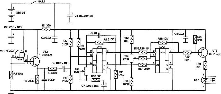
A circuit diagram of an assistant electrician.
The sensitive element of the electric field intensity is the field-effect transistor in a metal housing VT1, whose gate is connected to the housing. The magnitude of the induced signal is proportional to the electric field strength, High resistance resistor R2 prevents the accumulation of static charges. After going through ammatory repeater, performed on the transistor VT2, the signal is induced across the resistor R3. The capacitor C4 suppresses high frequency and pulse interference. Further, the signal flows through the resistor R4 and coupling capacitor C5 to the noninverting input 3 of operational amplifier (OA) DA1 (with the parameters and scope of this OU can be found in [2]). Resistors R5, R6 to create an artificial zero point of the resistors R7, R17 are used to install the necessary Micropower mode of OU DA1 and DA2 [2].
Variable resistor R9 (sensitivity) adjust the gain of the cascade of op-amp DA1. A capacitor C6 is the element of the correction frequency characteristic, and the resistor R11, the load appears to be for OU DA1. From terminal 6 of op-amp DA1 amplified signal through the resistor R15 is supplied to inverted input 2 of the comparator voltage on OU DA2. DA2 comparator compares the voltage output from the op-amp DA1 with exemplary voltage supplied to needvery input 3 of the comparator DA2. The magnitude of the reference voltage is adjusted by variable resistor R13 (“threshold”). Due to positive feedback through the resistor R18, the voltage comparator DA2 has small hysteresis, which increases the accuracy of its operation.
Output 6 signal DA2 is supplied to the power amplifier executed on the VT3 transistor, which works in a key mode.
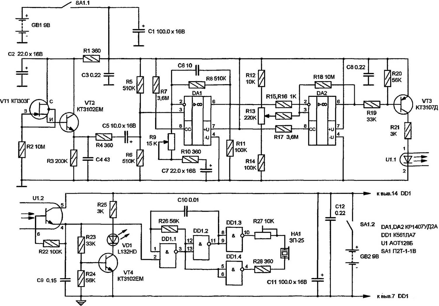
In the previously described prototype [1] this transistor is operated only led indication. Studies have shown that a simple connection to this additional transistor and aurally violates the stability of a Micropower op-amp DA1, DA2 due to the influence of display elements on the sensing inputs DA1 and DA2 increase in consumption current, which was unacceptable. This was the main obstacle to increasing the sensitivity of the NPE.
The problem was solved by separation of power: measuring part (VT1, VT2, DA1, DA2) from the GB1 battery 9V, and the led and sound indication from the other GB2 9V battery. Therefore, the impact of the indication on the measuring part has been removed. The connection between them is via transistor optocoupler U1. Signal transmitted through the led of the optocoupler, is allocated to the emitter of its phototransistor U1.2, the load of which carry series-connected resistors R23, R24. Capacitor C9 increases the resistance of the display unit. The VT4 transistor operating in key mode, inverts the signal and provides an indication of VD1 led the preparation of the device for operation (adjustment methodology will be discussed below), and the measurements. With the emitter of the phototransistor of the optocoupler U1.2 a signal also arrives at the launch of the scheme the tone generator, is made on the chip DD1.1 and DD1.2, which can be output at the resonant frequency of the piezo HA1 of type CP-25 selection of resistor R26, which significantly increases the volume of its sound. The oscillator frequency is determined by the formula:
F=0.5*1000000/(R26*C10),
where R26 is in kω, C10 — nF, f in Hz.
Buffer elements DD1.3, DD1.4 additionally boost the sound quality of the HA1. This is due to the improvement in generator excitation, a decrease in the duration of its fronts. Rigged a resistor R27 to adjust the volume level NA1.
PCB NPE (105×35 mm) made of unilateral flingo fiberglass thickness of 1.5 mm and placed in a plastic housing dimensions 130x75x25 mm. the sensor of electric field — a field-effect transistor VT1 is removed from the PCB to the front panel of the chassis.
To provide shielding of the printed circuit Board, the author has produced a body of fiberglass foil with a thickness of 2 mm. the overall point of the measuring part of the circuit is connected with copper foil inside the hull. To protect the protruding part of the body of the field effect transistor from touching nezaboravnim wires and metal parts, it is worn and taped a plastic sleeve.
Controls R9, R13, SA1 and diode VD1 displayed on the front panel of the unit. Piezo buzzer HA1 is located inside the housing on the circuit Board. In the side wall of the housing there is a hole under the fixed resistor R27. For 9-volt batteries GB1 and GB2 (type “Crown”, “Emery”) inside the case dedicated compartments.
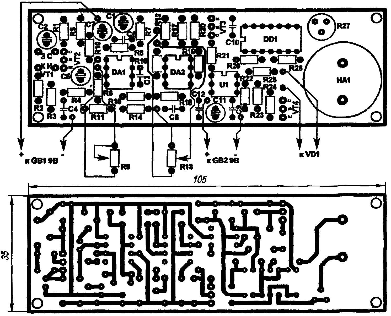
PCB NPE.
In standby mode the consumption of the measuring part of the scheme of NPE from the GB1 battery is not more than 0.2 mA and increased to 3 mA when triggered, the input led of the optocoupler U1.1.
The scheme of readout from the battery GB2 in standby mode not more than 0.1 mA, increasing to 3 mA when alarm led and audible indication.
The performance of NPE is saved by reducing the voltage of the battery GB1 and GB2 to 4 V.
When setting up IPPS might have to select values of resistors R8, R18 and R26. The transistor VT1 can be replaced by КП307Ж or from КП303, KP307. Instead of VT1 — VT4, marked on the diagram, you can use low-power silicon bipolar transistors of the corresponding structure. The variable resistors R9 and R13 type SPZ-4. A fixed resistor R27 is the type SP5-16ВА-0.25 W. The switch SA1 compact — type П2Т-1-1B. The following are the 3 modes of NPE.
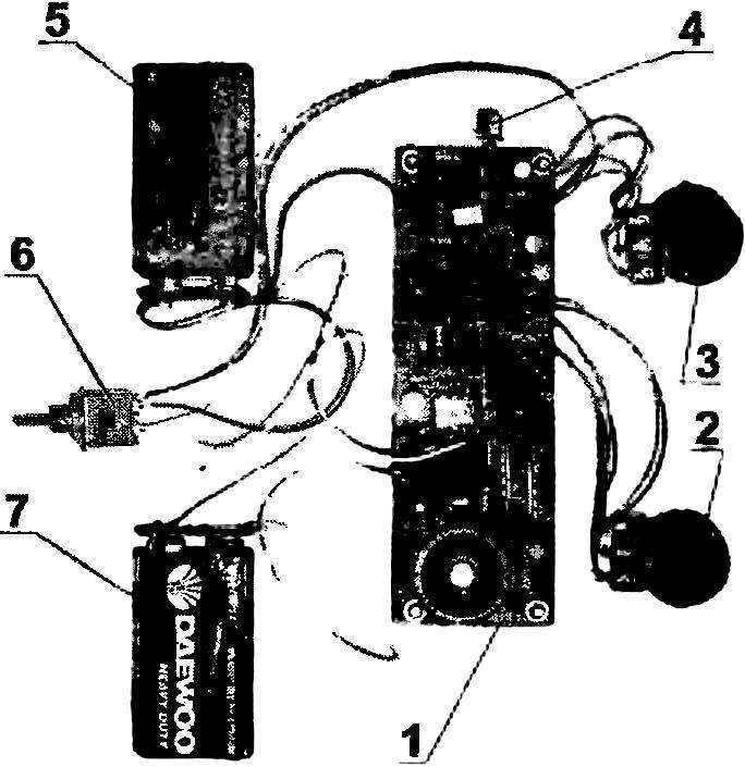
The elements and nodes of the NPE:
1 — PCB; 2 — potentiometer R13; 3 — potentiometer R9; 4 — field-effect transistor VT1; 5 — battery GB1; 6 — the switch SA1; 7 — battery GB2.
Mode phase tester. If the variable resistor R9 (“sensitivity”) set almost at the bottom (under the scheme) position, a R13 (“threshold”) — almost to the upper position, the gain induced on the sensor signal is minimum, and threshold maximum.
Starting position before the measurement — the lack of led and sound indication, which is achieved by appropriate adjustment of variable resistors R9 and R13, when the transducer is removed some distance from the source of AC electric field.
In this pre-set condition, NPE allows first ignition of the led VD1, and then the sound indication piezo HA1 to distinguish “phase” wire household power from “zero”. You must bring the sensor to the isolation of each of these wires.
Use this mode to calibrate the device, for example, carefully bringing the sensor to a household power outlet with the “phase” and “zero” wire.
Search mode hidden wiring. To find with the help of NPE hidden in the wall wiring, it is necessary to increase the gain op-amp DA1 moving the engine variable resistor R9 (“sensitivity”) to the top (under the scheme) and lowering the threshold of the comparator DA2 by moving the variable resistor R13 (“threshold”) down under the scheme.
Starting position before the measurement — the lack of led and sound indication, which is achieved by appropriate adjustment of variable resistors. When approaching the sensor to route the wires under the voltage readout begins to act.
When you search for hidden wiring should not touch even zaizolirovali sensor of the walls, inside of which it passes. The sensitivity of the device is sufficient to avoid false triggering NPE from interference of static electricity and interference.
Another advantage of this device is that on the background of network interference for example, in a block house, if configured, R9 and R13 can, with high sensitivity and selectivity, NPE, determine the route 4 energized wires. With similar devices that would be problematic.
Mode indicator of the electric field. With further increase of strengthening of OU DA1 and lowering the triggering threshold of the comparator DA2 fails to locate live wires and cables at a considerable distance from them. As in the previous cases, in the initial state of the device before measurement indication should be absent.
Configured appropriately, NPE, for example, may signal about the presence of the electric field at a distance of not less than three meters from a high voltage bus under voltage 10 kW. Instrument setup is not complicated, and when you work with him fairly quickly the necessary skills.
In the operation of IPP proved highly sensitive balanced device allowing for contactless measurement of alternating electric field both near and away from different purpose wires and cables under tension.
B. SOKOLOV, Protvino, Moscow oblast
Recommend to read
 WITH GUARANTEED ANGLE
Reground the blade plane for beginners is sheer torture. Not so just manually set the correct angle between the sand around and a piece of iron and withstand this angle throughout the... TAKE THE ROAD
I travel frequently, so I made myself comfortable Hiking hanger, which is even more compact folding, produced by industry. Of the device it is clear from the figure. The tube can be any,...
