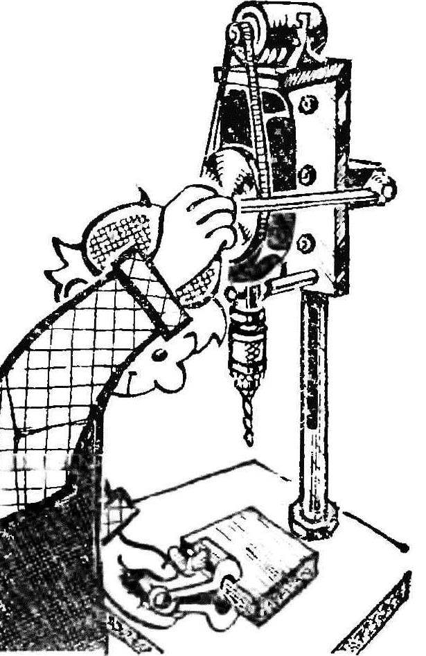
Offer for fans of DIY table homemade drill press using hand drill. On a solid base is mounted a hollow stand-tube, movably installed inside the stock. On the one hand, he sliced the rack to drive the vertical feed, and with another selected area for connection of the bracket with the guide bar through the longitudinal groove of the rack. On the bracket mounted hand drill and the motor. The drive from the drill motor is belt drive. Vertical supply node provides a mechanism assembled in a separate housing. The external dimensions of the machine depend on the chosen length of the strut and the base; the vertical stroke serves for the size — 100 mm.
Learn more about the details of the machine.
The base is a steel plate with dimensions of 320 X 320 X 8 mm. it is drilled hole d 35 mm under the counter and four threaded corners for the legs.
As a rack used thick-walled steel pipe with an outer d of 35 mm and an internal 23 mm, one end tapped M35 for mounting on the base. On the other milled longitudinal groove of a width of 14 mm (under the guide of the bracket) and a rectangular window for mounting the drive pinion vertical feed. Four radial holes M5 are intended for mounting on the front of the mechanism housing, a vertical feed.

 Offer for fans of DIY table homemade drill press using hand drill. On a solid base is mounted a hollow stand-tube, movably installed inside the stock. On the one hand, he sliced the rack to drive the vertical feed, and with another selected area for connection of the bracket with the guide bar through the longitudinal groove of the rack. On the bracket mounted hand drill and the motor. The drive from the drill motor is belt drive. Vertical supply node provides a mechanism assembled in a separate housing. The external dimensions of the machine depend on the chosen length of the strut and the base; the vertical stroke serves for the size — 100 mm.